2007 NISSAN TIIDA reverse
[x] Cancel search: reversePage 2957 of 5883
![NISSAN TIIDA 2007 Service Repair Manual EM-310
< DISASSEMBLY AND ASSEMBLY >[K9K]
CYLINDER HEAD
7. Place the guide tube plus push rod assembly on the valve stem
seal.
8. Push the valve stem seal down by tapping the top of the sleeve
with the NISSAN TIIDA 2007 Service Repair Manual EM-310
< DISASSEMBLY AND ASSEMBLY >[K9K]
CYLINDER HEAD
7. Place the guide tube plus push rod assembly on the valve stem
seal.
8. Push the valve stem seal down by tapping the top of the sleeve
with the](/manual-img/5/57395/w960_57395-2956.png)
EM-310
< DISASSEMBLY AND ASSEMBLY >[K9K]
CYLINDER HEAD
7. Place the guide tube plus push rod assembly on the valve stem
seal.
8. Push the valve stem seal down by tapping the top of the sleeve
with the palm of your hand until the guide tube touches the cylin-
der head.
9. Repeat these operations for all the valves.
10. Install the valve springs and upper cups using valve spring com-
pressor.
11. Install the keys using tweezers.
12. Install in the reverse order of removal after this step.
CleaningINFOID:0000000001381511
It is very important not to scratch the gasket faces of any aluminium components.
Use suitable tool to dissolve any part of the seal which remains stuck to the metal surface.
Apply the dissolving product to the part to be cleaned, wait approximately 10 minutes, then remove it using a
wooden spatula.
Wear gloves while carrying out this operation.
Do not allow this dissolving product to drip on to the paintwork.
Great care should be taken when performing this operation, to prevent foreign objects from entering
the pipes taking oil under pressure to the camshafts (pipes in both the cylinder head and its cover)
and the oil return pipes.
Failure to follow these instructions could lead to the blocking of the oilways, resulting in rapid and
serious damage to the engine.
InspectionINFOID:0000000001381512
INSPECTION AFTER REMOVAL
Cylinder Head Distortion
NOTE:
When performing this inspection, cylinder block distortion should be also checked. Refer to EM-330, "
Inspec-
tion".
1. Wipe off engine oil and remove water scale (like deposit), gasket, sealant, carbon, etc. with a scraper.
CAUTION:
MBIB0425E
MBIB0416E
Page 2962 of 5883
![NISSAN TIIDA 2007 Service Repair Manual CYLINDER BLOCK
EM-315
< DISASSEMBLY AND ASSEMBLY >[K9K]
C
D
E
F
G
H
I
J
K
L
MA
EM
N
P O
1. Install the ring gear stopper [SST: KV113B0060 (Mot. 582-01)].
2. Remove the clutch housing.
3. Remove the fl NISSAN TIIDA 2007 Service Repair Manual CYLINDER BLOCK
EM-315
< DISASSEMBLY AND ASSEMBLY >[K9K]
C
D
E
F
G
H
I
J
K
L
MA
EM
N
P O
1. Install the ring gear stopper [SST: KV113B0060 (Mot. 582-01)].
2. Remove the clutch housing.
3. Remove the fl](/manual-img/5/57395/w960_57395-2961.png)
CYLINDER BLOCK
EM-315
< DISASSEMBLY AND ASSEMBLY >[K9K]
C
D
E
F
G
H
I
J
K
L
MA
EM
N
P O
1. Install the ring gear stopper [SST: KV113B0060 (Mot. 582-01)].
2. Remove the clutch housing.
3. Remove the flywheel.
4. Remove the oil pan bolt in reverse order as shown.
5. Remove the oil level sensor.
6. Remove the oil pump.
7. Remove the crankshaft cover.
8. Remove the water pump.
MBIB0397E
MBIB0439E
MBIB1257E
MBIB0442E
MBIB0443E
Page 2992 of 5883
![NISSAN TIIDA 2007 Service Repair Manual EX-6
< ON-VEHICLE REPAIR >[HR16DE]
EXHAUST SYSTEM
2. Disconnect each joint and mounting rubber.
INSTALLATION
Installation is in the reverse order of removal.
CAUTION:
Always replace exhaust gaskets NISSAN TIIDA 2007 Service Repair Manual EX-6
< ON-VEHICLE REPAIR >[HR16DE]
EXHAUST SYSTEM
2. Disconnect each joint and mounting rubber.
INSTALLATION
Installation is in the reverse order of removal.
CAUTION:
Always replace exhaust gaskets](/manual-img/5/57395/w960_57395-2991.png)
EX-6
< ON-VEHICLE REPAIR >[HR16DE]
EXHAUST SYSTEM
2. Disconnect each joint and mounting rubber.
INSTALLATION
Installation is in the reverse order of removal.
CAUTION:
Always replace exhaust gaskets and seal bearings with new ones when installing.
Discard any heated oxygen sensor 2 which has been dropped from a height of more than 0.5 m (19.7
in) onto a hard surface such as a concrete floor; use a new one.
Before installing a new heated oxygen sensor 2, clean exhaust system threads using the heated oxy-
gen sensor thread cleaner and apply anti-seize lubricant (commercial service tool).
Do not over tighten heated oxygen sensor 2. Doing so may cause damage to the heated oxygen sen-
sor 2, resulting in the “MIL” coming on.
Remove deposits from the sealing surface of each connection. Connect them securely to avoid
exhaust leakage.
Temporarily tighten nuts on the exhaust manifold side and bolts on the vehicle side. Check each part
for unusual interference, and then tighten them to the specified torque.
When installing each mounting rubber, avoid twisting or unusual extension in up/down and right/left
directions.
Exhaust Manifold to Exhaust Front Tube
1. Securely insert seal bearing (2) into exhaust manifold (1) side in
the direction shown.
Exhaust front tube (5)
CAUTION:
Be careful not to damage seal bearing surface when install-
ing.
2. Install spring (3), tighten nut (4).
Be careful that the stud bolt nut does not interfere with the
flanged area ( ).
Make sure the spring (3) sits properly on the flange surface by
aligning it to the locator dimples.
Exhaust Front Tube to Center Muffler
1. Securely insert seal bearing (2) into exhaust front tube (1) side
in the direction shown.
Center muffler (5)
CAUTION:
Be careful not to damage seal bearing surface when install-
ing.
2. With spring (3), tighten bolt (4).
Be careful that the stud bolt does not interfere with the flanged
area ( ).
Make sure the spring (3) sits properly on the flange surface by
aligning it to the locator dimples.
InspectionINFOID:0000000001700348
INSPECTION AFTER INSTALLATION
With the engine running, check exhaust tube joints for exhaust leakage and unusual noise.
Check to ensure that brackets and mounting rubbers are installed properly and free from undue stress.
Improper installation could result in excessive noise and vibration.
PBIC3797E
PBIC3798E
Page 2997 of 5883
![NISSAN TIIDA 2007 Service Repair Manual EXHAUST SYSTEM
EX-11
< ON-VEHICLE REPAIR >[MR18DE]
C
D
E
F
G
H
I
J
K
L
MA
EX
N
P O
2. Disconnect each joint and mounting rubber.
INSTALLATION
Installation is in the reverse order of removal.
CAUTION: NISSAN TIIDA 2007 Service Repair Manual EXHAUST SYSTEM
EX-11
< ON-VEHICLE REPAIR >[MR18DE]
C
D
E
F
G
H
I
J
K
L
MA
EX
N
P O
2. Disconnect each joint and mounting rubber.
INSTALLATION
Installation is in the reverse order of removal.
CAUTION:](/manual-img/5/57395/w960_57395-2996.png)
EXHAUST SYSTEM
EX-11
< ON-VEHICLE REPAIR >[MR18DE]
C
D
E
F
G
H
I
J
K
L
MA
EX
N
P O
2. Disconnect each joint and mounting rubber.
INSTALLATION
Installation is in the reverse order of removal.
CAUTION:
Always replace exhaust gaskets and seal bearings with new ones when installing.
Discard any heated oxygen sensor 2 which has been dropped from a height of more than 0.5 m (19.7
in) onto a hard surface such as a concrete floor; use a new one.
Before installing a new heated oxygen sensor 2, clean exhaust system threads using the heated oxy-
gen sensor thread cleaner and apply anti-seize lubricant (commercial service tool).
Do not over tighten heated oxygen sensor 2. Doing so may cause damage to the heated oxygen sen-
sor 2, resulting in the “MIL” coming on.
Remove deposits from the sealing surface of each connection. Connect them securely to avoid
exhaust leakage.
Temporarily tighten nuts on the exhaust manifold side and bolts on the vehicle side. Check each part
for unusual interference, and then tighten them to the specified torque.
When installing each mounting rubber, avoid twisting or unusual extension in up/down and right/left
directions.
Exhaust Manifold to Exhaust Front Tube
1. Securely insert seal bearing (2) into exhaust manifold (1) side in
the direction shown.
Exhaust front tube (5)
CAUTION:
Be careful not to damage seal bearing surface when install-
ing.
2. Install spring (3), tighten nut (4).
Be careful that the stud bolt nut does not interfere with the
flanged area ( ).
Make sure the spring (3) sits properly on the flange surface by
aligning it to the locator dimples.
Exhaust Front Tube to Center Muffler
1. Securely insert seal bearing (2) into exhaust front tube (1) side
in the direction shown.
Center muffler (5)
CAUTION:
Be careful not to damage seal bearing surface when install-
ing.
2. With spring (3), tighten bolt (4).
Be careful that the stud bolt does not interfere with the flanged
area ( ).
Make sure the spring (3) sits properly on the flange surface by
aligning it to the locator dimples.
INSPECTION AFTER INSTALLATION
With the engine running, check exhaust tube joints for exhaust leakage and unusual noise.
Check to ensure that brackets and mounting rubbers are installed properly and free from undue stress.
Improper installation could result in excessive noise and vibration.
InspectionINFOID:0000000001696389
INSPECTION AFTER INSTALLATION
Make sure clearance between tail tube and rear bumper is even.
With engine running, check exhaust tube joints for gas leakage and unusual noises.
Check to ensure that mounting brackets and mounting rubbers are installed properly and free from undue
stress. Improper installation could result in excessive noise and vibration.
PBIC3797E
PBIC3798E
Page 3000 of 5883
![NISSAN TIIDA 2007 Service Repair Manual EX-14
< ON-VEHICLE REPAIR >[K9K]
EXHAUST SYSTEM
ON-VEHICLE REPAIR
EXHAUST SYSTEM
ComponentINFOID:0000000001700347
Removal and InstallationINFOID:0000000001696393
CAUTION:
Be sure to use genuine exha NISSAN TIIDA 2007 Service Repair Manual EX-14
< ON-VEHICLE REPAIR >[K9K]
EXHAUST SYSTEM
ON-VEHICLE REPAIR
EXHAUST SYSTEM
ComponentINFOID:0000000001700347
Removal and InstallationINFOID:0000000001696393
CAUTION:
Be sure to use genuine exha](/manual-img/5/57395/w960_57395-2999.png)
EX-14
< ON-VEHICLE REPAIR >[K9K]
EXHAUST SYSTEM
ON-VEHICLE REPAIR
EXHAUST SYSTEM
ComponentINFOID:0000000001700347
Removal and InstallationINFOID:0000000001696393
CAUTION:
Be sure to use genuine exhaust system parts or equivalents which are specially designed for heat
resistance, corrosion resistance and shape.
Perform the operation with the exhaust system fully cooled down because the system is still hot just
after the engine stops.
Be careful not to cut your hand on the insulator edge.
REMOVAL
Disconnect each joint and mounting.
INSTALLATION
Installation is in the reverse order of removal.
CAUTION:
Always replace exhaust gaskets and seal bearings with new ones when installing.
Remove deposits from the sealing surface of each connection. Connect them securely to avoid
exhaust leakage.
Temporarily tighten nuts on the exhaust manifold side and bolts on the vehicle side. Check each part
for unusual interference, and then tighten them to the specified torque.
1. Main muffler 2. Mounting rubber 3. Ring gasket
4. Center muffler 5. Spring 6. Seal bearing
7. Exhaust front tube 8. Stud bolt 9. Ground cable
AWBIA0159GB
Page 3086 of 5883

HEADLAMP
EXL-85
< ON-VEHICLE REPAIR >
C
D
E
F
G
H
I
J
K
MA
B
EXL
N
O
P
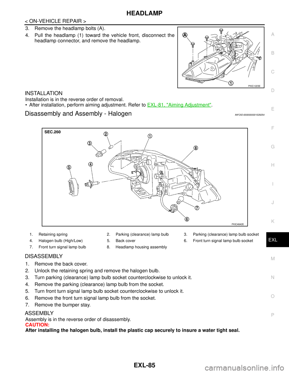
3. Remove the headlamp bolts (A).
4. Pull the headlamp (1) toward the vehicle front, disconnect the
headlamp connector, and remove the headlamp.
INSTALLATION
Installation is in the reverse order of removal.
After installation, perform aiming adjustment. Refer to EXL-81, "
Aiming Adjustment".
Disassembly and Assembly - HalogenINFOID:0000000001529254
DISASSEMBLY
1. Remove the back cover.
2. Unlock the retaining spring and remove the halogen bulb.
3. Turn parking (clearance) lamp bulb socket counterclockwise to unlock it.
4. Remove the parking (clearance) lamp bulb from the socket.
5. Turn front turn signal lamp bulb socket counterclockwise to unlock it.
6. Remove the front turn signal lamp bulb from the socket.
7. Remove the bumper stay.
ASSEMBLY
Assembly is in the reverse order of disassembly.
CAUTION:
After installing the halogen bulb, install the plastic cap securely to insure a water tight seal.
PKIC1223E
1. Retaining spring 2. Parking (clearance) lamp bulb 3. Parking (clearance) lamp bulb socket
4. Halogen bulb (High/Low) 5. Back cover 6. Front turn signal lamp bulb socket
7. Front turn signal lamp bulb 8. Headlamp housing assembly
PKIC4642E
Page 3087 of 5883

EXL-86
< ON-VEHICLE REPAIR >
HEADLAMP
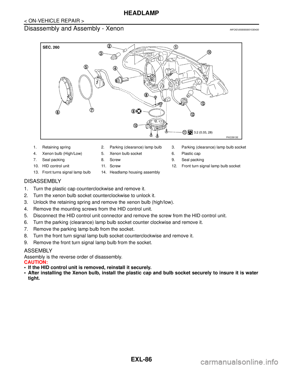
Disassembly and Assembly - Xenon
INFOID:0000000001530430
DISASSEMBLY
1. Turn the plastic cap counterclockwise and remove it.
2. Turn the xenon bulb socket counterclockwise to unlock it.
3. Unlock the retaining spring and remove the xenon bulb (high/low).
4. Remove the mounting screws from the HID control unit.
5. Disconnect the HID control unit connector and remove the screw from the HID control unit.
6. Turn the parking (clearance) lamp bulb socket counter clockwise and remove it.
7. Remove the parking lamp bulb from the socket.
8. Turn the front turn signal lamp bulb socket counterclockwise and remove it.
9. Remove the front turn signal lamp bulb from the socket.
ASSEMBLY
Assembly is the reverse order of disassembly.
CAUTION:
If the HID control unit is removed, reinstall it securely.
After installing the Xenon bulb, install the plastic cap and bulb socket securely to insure it is water
tight.
1. Retaining spring 2. Parking (clearance) lamp bulb 3. Parking (clearance) lamp bulb socket
4. Xenon bulb (High/Low) 5. Xenon bulb socket 6. Plastic cap
7. Seal packing 8. Screw 9. Seal packing
10. HID control unit 11. Screw 12. Front turn signal lamp bulb socket
13. Front turns signal lamp bulb 14. Headlamp housing assembly
PKIC0913E
Page 3088 of 5883

FRONT FOG LAMP
EXL-87
< ON-VEHICLE REPAIR >
C
D
E
F
G
H
I
J
K
MA
B
EXL
N
O
P
FRONT FOG LAMP
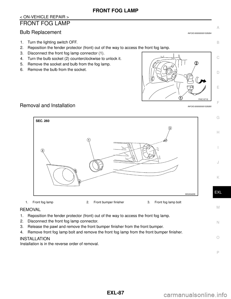
Bulb ReplacementINFOID:0000000001529284
1. Turn the lighting switch OFF.
2. Reposition the fender protector (front) out of the way to access the front fog lamp.
3. Disconnect the front fog lamp connector (1).
4. Turn the bulb socket (2) counterclockwise to unlock it.
5. Remove the socket and bulb from the fog lamp.
6. Remove the bulb from the socket.
Removal and InstallationINFOID:0000000001529285
REMOVAL
1. Reposition the fender protector (front) out of the way to access the front fog lamp.
2. Disconnect the front fog lamp connector.
3. Release the pawl and remove the front bumper finisher from the front bumper.
4. Remove front fog lamp bolt and remove the front fog lamp from the front bumper finisher.
INSTALLATION
Installation is in the reverse order of removal.
PKIC1071E
1. Front fog lamp 2. Front bumper finisher 3. Front fog lamp bolt
WKIA5420E