2007 NISSAN TIIDA motor mount
[x] Cancel search: motor mountPage 2127 of 5883
![NISSAN TIIDA 2007 Service Repair Manual EC-778
< FUNCTION DIAGNOSIS >[MR18DE]
ON BOARD DIAGNOSTIC (OBD) SYSTEM
*: Leaving cooling fan OFF with CONSULT-III while engine is running may cause the engine to overheat.
DTC & SRT CONFIRMATION MODE](/manual-img/5/57395/w960_57395-2126.png "NISSAN TIIDA 2007 Service Repair Manual EC-778
< FUNCTION DIAGNOSIS >[MR18DE]
ON BOARD DIAGNOSTIC (OBD) SYSTEM
*: Leaving cooling fan OFF with CONSULT-III while engine is running may cause the engine to overheat.
DTC & SRT CONFIRMATION MODE")
EC-778
< FUNCTION DIAGNOSIS >[MR18DE]
ON BOARD DIAGNOSTIC (OBD) SYSTEM
*: Leaving cooling fan OFF with CONSULT-III while engine is running may cause the engine to overheat.
DTC & SRT CONFIRMATION MODE
SRT STATUS Mode
For details, refer to EC-760, "Diagnosis Description".
SRT WORK SUPPORT Mode
This mode enables a technician to drive a vehicle to set the SRT while monitoring the SRT status.
DTC WORK SUPPORT Mode
TEST ITEM CONDITION JUDGEMENT CHECK ITEM (REMEDY)
FUEL INJECTION Engine: Return to the original
trouble condition
Change the amount of fuel injec-
tion using CONSULT-III.If trouble symptom disappears, see
CHECK ITEM. Harness and connectors
Fuel injector
Heated oxygen sensor 1
IGNITION TIMING Engine: Return to the original
trouble condition
Timing light: Set
Retard the ignition timing using
CONSULT-III.If trouble symptom disappears, see
CHECK ITEM. Perform Idle Air Volume Learning.
POWER BALANCE Engine: After warming up, idle
the engine.
A/C switch OFF
Shift lever:Neutral
Cut off each fuel injector signal
one at a time using CONSULT-
III.Engine runs rough or dies. Harness and connectors
Compression
Fuel injector
Power transistor
Spark plug
Ignition coil
COOLING FAN* Ignition switch: ON
Turn the cooling fan “LOW”, “HI”
and “OFF” CONSULT-III.Cooling fan moves and stops. Harness and connectors
IPDM E/R (Cooling fan relay)
Cooling fan motor
ENG COOLANT
TEMP Engine: Return to the original
trouble condition
Change the engine coolant tem-
perature using CONSULT-III.If trouble symptom disappears, see
CHECK ITEM. Harness and connectors
Engine coolant temperature sen-
sor
Fuel injector
FUEL PUMP RELAY Ignition switch: ON (Engine
stopped)
Turn the fuel pump relay “ON”
and “OFF” using CONSULT-III
and listen to operating sound.Fuel pump relay makes the operat-
ing sound. Harness and connectors
Fuel pump relay
PURG VOL CONT/V Engine: After warming up, run
engine at 1,500 rpm.
Change the EVAP canister
purge volume control solenoid
valve opening percent using
CONSULT-III.Engine speed changes according
to the opening percent. Harness and connectors
Solenoid valve
V/T ASSIGN ANGLE Engine: Return to the original
trouble condition
Change intake valve timing us-
ing CONSULT-III.If trouble symptom disappears, see
CHECK ITEM. Harness and connectors
Intake valve timing control sole-
noid valve
Test mode Test item Condition Reference page
HO2S1HO2S1 (B1) P0133
Refer to corresponding
trouble diagnosis for DTC.EC-817
HO2S1 (B1) P0134EC-823
HO2S1 (B1) P1143EC-823
HO2S1 (B1) P1144EC-901
HO2S2HO2S2 (B1) P0139EC-835HO2S2 (B1) P1146EC-906
HO2S2 (B1) P1147EC-912
Page 2739 of 5883
![NISSAN TIIDA 2007 Service Repair Manual EM-92
< REMOVAL AND INSTALLATION >[HR16DE]
ENGINE ASSEMBLY
4. Remove engine mounting insulator (RH) (1), engine mounting
bracket (RH) (2) and engine mounting stay (3).
5. Remove engine mounting throug](/manual-img/5/57395/w960_57395-2738.png "NISSAN TIIDA 2007 Service Repair Manual EM-92
< REMOVAL AND INSTALLATION >[HR16DE]
ENGINE ASSEMBLY
4. Remove engine mounting insulator (RH) (1), engine mounting
bracket (RH) (2) and engine mounting stay (3).
5. Remove engine mounting throug")
EM-92
< REMOVAL AND INSTALLATION >[HR16DE]
ENGINE ASSEMBLY
4. Remove engine mounting insulator (RH) (1), engine mounting
bracket (RH) (2) and engine mounting stay (3).
5. Remove engine mounting through bolt-securing nut (A).
6. Carefully lower jack, or raise lift to remove the engine and the transaxle assembly.
CAUTION:
Make sure that no part interferes with the vehicle side.
Before and during this lifting, always check if any harnesses are left connected.
During the removal, always be careful to prevent the vehicle from falling off the lift due to
changes in the center of gravity.
If necessary, support the vehicle by setting jack or suitable tool at the rear.
Separation
1. Remove starter motor. Refer to STR-13, "Removal and Installation".
2. Lift with a hoist and separate the engine from the transaxle assembly. Refer to EM-89, "
Exploded View".
INSTALLATION
Installation is in the reverse order of removal.
Do not allow engine oil to get on engine mounting insulator. Be careful not to damage engine mounting insu-
lator.
Make sure that each mounting insulator is seated properly, and tighten mounting nuts and bolts.
Tighten engine mounting insulator (RH) bolts in the numerical
order shown.
InspectionINFOID:0000000001381426
INSPECTION AFTER INSTALLATION
Inspection for Leaks
Before starting engine, check oil/fluid levels including engine coolant and engine oil. If less than required
quantity, fill to the specified level. Refer to MA-19, "
Fluids and Lubricants".
Use procedure below to check for fuel leakage.
- Turn ignition switch “ON” (with engine stopped). With fuel pressure applied to fuel piping, check for fuel leak-
age at connection points.
- Start engine. With engine speed increased, check again for fuel leakage at connection points.
Run engine to check for unusual noise and vibration.
Warm up engine thoroughly to make sure there is no leakage of fuel, exhaust gases, or any oil/fluids includ-
ing engine oil and engine coolant.
Bleed air from lines and hoses of applicable lines, such as in cooling system.
After cooling down engine, again check oil/fluid levels including engine oil and engine coolant. Refill to the
specified level, if necessary.
4 : Engine mounting insulator (LH)
JPBIA0512ZZ
: Vehicle front
JPBIA0280ZZ
Page 2856 of 5883
![NISSAN TIIDA 2007 Service Repair Manual ENGINE ASSEMBLY
EM-209
< REMOVAL AND INSTALLATION >[MR18DE]
C
D
E
F
G
H
I
J
K
L
MA
EM
N
P O
24. Remove the intake manifold to prevent the hanging chain from interfering. Refer to EM-156, "Removal
and](/manual-img/5/57395/w960_57395-2855.png "NISSAN TIIDA 2007 Service Repair Manual ENGINE ASSEMBLY
EM-209
< REMOVAL AND INSTALLATION >[MR18DE]
C
D
E
F
G
H
I
J
K
L
MA
EM
N
P O
24. Remove the intake manifold to prevent the hanging chain from interfering. Refer to EM-156, \"Removal
and")
ENGINE ASSEMBLY
EM-209
< REMOVAL AND INSTALLATION >[MR18DE]
C
D
E
F
G
H
I
J
K
L
MA
EM
N
P O
24. Remove the intake manifold to prevent the hanging chain from interfering. Refer to EM-156, "Removal
and Installation".
25. Install engine slinger to cylinder head front left side (A) and rear
right side (B) and support the engine position with a hoist.
26. Support engine and transaxle assembly with a hoist and secure the engine in appropriate position.
27. Use a manual lift table caddy (A) or equivalently rigid tool such
as a transmission jack. Securely support bottom of the engine
and the transaxle, and simultaneously adjust hoist tension.
CAUTION:
Put a piece of wood or something similar as the supporting
surface, secure a completely stable condition.
28. Remove torque rod (RH) (1), engine insulator (RH) (2) and
engine bracket (RH) (3).
29. Remove engine through bolt-securing nut (C).
30. Remove the engine and the transaxle assembly from the vehicle downward by carefully operating sup-
porting tools.
CAUTION:
During the operation, make sure that no part interferes with the vehicle side.
Before and during this lifting, always check if any harnesses are left connected.
During the removal operation, always be careful to prevent the vehicle from falling off the lift due
to changes in the center of gravity.
If necessary, support the vehicle by setting jack or suitable tool at the rear.
During operation, securely support the engine by placing a piece of wood under the engine oil
pan and transaxle oil pan. Securely support the engine slingers with a hoist.
31. When the engine hoisting is not performed simultaneously, install engine slinger to cylinder head front left
side and rear right side. Refer to EM-207, "
Component".
32. Remove starter motor. Refer to STR-24, "
Removal and Installation".
33. Lift with a hoist and position above engine.
34. Separate the engine and the transaxle. Refer to EM-207, "
Component" .
INSTALLATION
Note the following, and install in the reverse order of removal.
Do not allow engine oil to get on engine mounting insulator. Be careful not to damage engine mounting insu-
lator.
: Engine front
Slinger bolts : 25.5 N·m (2.6 kg-m, 19 ft-lb)
LBIA0461E
PBIC3223J
4 : Engine insulator (LH)
A : Engine front side
B : Transaxle side
WBIA0784E
Page 2951 of 5883
![NISSAN TIIDA 2007 Service Repair Manual EM-304
< REMOVAL AND INSTALLATION >[K9K]
ENGINE ASSEMBLY
1. Install engine slingers (1) into front right of cylinder head and
engine slinger (2) into rear left of cylinder head.
2. Remove upper torque](/manual-img/5/57395/w960_57395-2950.png "NISSAN TIIDA 2007 Service Repair Manual EM-304
< REMOVAL AND INSTALLATION >[K9K]
ENGINE ASSEMBLY
1. Install engine slingers (1) into front right of cylinder head and
engine slinger (2) into rear left of cylinder head.
2. Remove upper torque")
EM-304
< REMOVAL AND INSTALLATION >[K9K]
ENGINE ASSEMBLY
1. Install engine slingers (1) into front right of cylinder head and
engine slinger (2) into rear left of cylinder head.
2. Remove upper torque rod.
3. Use a manual lift table caddy (commercial service tool) or equiv-
alently rigid tool such as a jack or trestle. Securely support bot-
tom of engine and transaxle.
CAUTION:
Put a piece of wood or something similar at the supporting
surface to secure a stable condition.
4. Remove RH and LH engine mounting bolts.
5. Remove engine and transaxle assembly from vehicle downward
by carefully operating supporting tools.
CAUTION:
During the operation, make sure that no part interferes with body side.
Before and during this lifting, always check if any harnesses are left connected.
During the removal operation, always be careful to prevent vehicle from falling off the lift due to
changes in the center of gravity.
If necessary, support vehicle by setting a jack or equivalent tool at the rear.
Separation Work
CAUTION:
During the operation, secure the engine by placing a piece of wood under the engine oil pan and tran-
saxle and lift the engine using a suitable tool.
1. Remove starter motor.
2. Separate engine and transaxle.
3. Lift the engine with a suitable tool and separate the engine from the transaxle assembly. Refer to EM-302,
"Exploded View".
INSTALLATION
Installation is in the reverse order of removal.
Do not allow oil to get on mounting insulator. Be careful not to damage mounting insulator.
When installation directions are specified, install parts according to the direction marks on them referring to
exploded views.
Make sure that each mounting insulator is seated properly, and tighten mounting bolts and nuts.
InspectionINFOID:0000000001381506
INSPECTION AFTER INSTALLATION
Before starting engine check the levels of coolant, lubricants and oils. Fill to the specified level.
Before starting engine, bleed air from fuel piping. Refer to EM-287, "
Removal and Installation".
Run engine to check for unusual noise and vibration.
Warm up engine thoroughly to make sure there is no leakage of coolant, lubricants, oil, fuel and exhaust
gas.
Bleed air from passages in pipes and tubes of applicable lines.
MBIB9022E
Page 3439 of 5883
![NISSAN TIIDA 2007 Service Repair Manual HAC-106
< COMPONENT DIAGNOSIS >[AUTO AIR CONDITIONER (W/O NAVI)]
MODE DOOR MOTOR
COMPONENT DIAGNOSIS
MODE DOOR MOTOR
System DescriptionINFOID:0000000001547404
SYSTEM DESCRIPTION
Component Parts
Mode d](/manual-img/5/57395/w960_57395-3438.png "NISSAN TIIDA 2007 Service Repair Manual HAC-106
< COMPONENT DIAGNOSIS >[AUTO AIR CONDITIONER (W/O NAVI)]
MODE DOOR MOTOR
COMPONENT DIAGNOSIS
MODE DOOR MOTOR
System DescriptionINFOID:0000000001547404
SYSTEM DESCRIPTION
Component Parts
Mode d")
HAC-106
< COMPONENT DIAGNOSIS >[AUTO AIR CONDITIONER (W/O NAVI)]
MODE DOOR MOTOR
COMPONENT DIAGNOSIS
MODE DOOR MOTOR
System DescriptionINFOID:0000000001547404
SYSTEM DESCRIPTION
Component Parts
Mode door control system components are:
Front air control
Mode door motor
In-vehicle sensor
Ambient sensor
Sunload sensor
System Operation
The front air control receives data from each of the sensors. When a drive signal is input from front air control
to door motor, a step motor built into the door motor rotates according to the drive signal, and then stops at the
position of target door.
Mode door changes to manual select mode by pressing MODE/DEF switch of the controller. That allows mode
door to be fixed.
Pressing AUTO switch allows automatic control by front air control, and mode door is fixed in the FOOT posi-
tion by pressing OFF switch.
During automatic operation of mode door, mode door position (VENT, B/L, FOOT) is selected according to the
temperature of discharge air calculated by front air control based on the target opening angle of air mix door
and the amount of sunload. And only when ambient temperature is extremely low with the mode door in the
FOOT position, D/F is selected and prevents windshield fogging.
AWIIA0290GB
Page 3447 of 5883
![NISSAN TIIDA 2007 Service Repair Manual HAC-114
< COMPONENT DIAGNOSIS >[AUTO AIR CONDITIONER (W/O NAVI)]
INTAKE DOOR MOTOR
INTAKE DOOR MOTOR
System DescriptionINFOID:0000000001547411
SYSTEM DESCRIPTION
Component Parts
Intake door control sy](/manual-img/5/57395/w960_57395-3446.png "NISSAN TIIDA 2007 Service Repair Manual HAC-114
< COMPONENT DIAGNOSIS >[AUTO AIR CONDITIONER (W/O NAVI)]
INTAKE DOOR MOTOR
INTAKE DOOR MOTOR
System DescriptionINFOID:0000000001547411
SYSTEM DESCRIPTION
Component Parts
Intake door control sy")
HAC-114
< COMPONENT DIAGNOSIS >[AUTO AIR CONDITIONER (W/O NAVI)]
INTAKE DOOR MOTOR
INTAKE DOOR MOTOR
System DescriptionINFOID:0000000001547411
SYSTEM DESCRIPTION
Component Parts
Intake door control system components are: Front air control
Intake door motor
In-vehicle sensor
Ambient sensor
Sunload sensor
Intake sensor
ECM
System Operation
Suction opening is basically fixed in the position FRESH when DEF switch, FRE switch, or OFF switch (only at
the time of REC switch OFF) is pressed or when A/C switch is OFF. It is fixed in the position RECIRCULATION
when REC switch is pressed. It is automatically controlled at all other times.
During automatic control of suction opening, any of FRESH, 20% FRESH and RECIRCULATION is selected
according to the target opening angle of air mix door calculated by front air control based on the in-vehicle
temperature, ambient temperature and the amount of sunload.
Intake Door Control Specification
COMPONENT DESCRIPTION
Intake Door Motor
AWIIA0294GB
AWIIA0295GB
Page 3552 of 5883
![NISSAN TIIDA 2007 Service Repair Manual MODE DOOR MOTOR
HAC-219
< COMPONENT DIAGNOSIS >[AUTO AIR CONDITIONER (W/NAVI)]
C
D
E
F
G
H
J
K
L
MA
B
HAC
N
O
P
COMPONENT DIAGNOSIS
MODE DOOR MOTOR
System DescriptionINFOID:0000000001547326
SYSTEM DES](/manual-img/5/57395/w960_57395-3551.png "NISSAN TIIDA 2007 Service Repair Manual MODE DOOR MOTOR
HAC-219
< COMPONENT DIAGNOSIS >[AUTO AIR CONDITIONER (W/NAVI)]
C
D
E
F
G
H
J
K
L
MA
B
HAC
N
O
P
COMPONENT DIAGNOSIS
MODE DOOR MOTOR
System DescriptionINFOID:0000000001547326
SYSTEM DES")
MODE DOOR MOTOR
HAC-219
< COMPONENT DIAGNOSIS >[AUTO AIR CONDITIONER (W/NAVI)]
C
D
E
F
G
H
J
K
L
MA
B
HAC
N
O
P
COMPONENT DIAGNOSIS
MODE DOOR MOTOR
System DescriptionINFOID:0000000001547326
SYSTEM DESCRIPTION
Component Parts
Mode door control system components are:
Front air control
Mode door motor
In-vehicle sensor
Ambient sensor
Sunload sensor
System Operation
The front air control receives data from each of the sensors. When a drive signal is input from front air control
to door motor, a step motor built into the door motor rotates according to the drive signal, and then stops at the
position of target door.
Mode door changes to manual select mode by turning mode control dial of the controller. That allows mode
door to be fixed.
Pressing AUTO switch allows automatic control by front air control, and mode door is fixed in the FOOT posi-
tion by pressing OFF switch.
During automatic operation of mode door, mode door position (VENT, B/L, FOOT) is selected according to the
temperature of blow-off wind calculated by front air control based on the target opening angle of air mix door
and the amount of solar radiation. And only when ambient temperature is extremely low with the mode door in
the FOOT position, D/F is selected and prevents windshield fogging.
AWIIA0333GB
Page 4865 of 5883
ST-10
< ON-VEHICLE REPAIR >
STEERING COLUMN
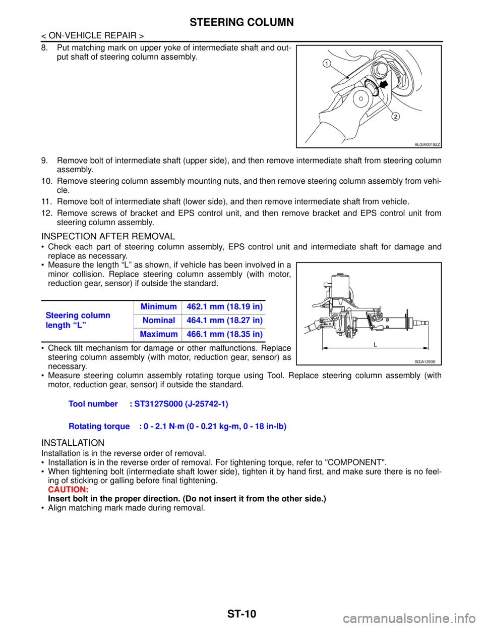
8. Put matching mark on upper yoke of intermediate shaft and out-
put shaft of steering column assembly.
9. Remove bolt of intermediate shaft (upper side), and then remove intermediate shaft from steering column
assembly.
10. Remove steering column assembly mounting nuts, and then remove steering column assembly from vehi-
cle.
11. Remove bolt of intermediate shaft (lower side), and then remove intermediate shaft from vehicle.
12. Remove screws of bracket and EPS control unit, and then remove bracket and EPS control unit from
steering column assembly.
INSPECTION AFTER REMOVAL
Check each part of steering column assembly, EPS control unit and intermediate shaft for damage and
replace as necessary.
Measure the length “L” as shown, if vehicle has been involved in a
minor collision. Replace steering column assembly (with motor,
reduction gear, sensor) if outside the standard.
Check tilt mechanism for damage or other malfunctions. Replace
steering column assembly (with motor, reduction gear, sensor) as
necessary.
Measure steering column assembly rotating torque using Tool. Replace steering column assembly (with
motor, reduction gear, sensor) if outside the standard.
INSTALLATION
Installation is in the reverse order of removal.
Installation is in the reverse order of removal. For tightening torque, refer to "COMPONENT".
When tightening bolt (intermediate shaft lower side), tighten it by hand first, and make sure there is no feel-
ing of sticking or galling before final tightening.
CAUTION:
Insert bolt in the proper direction. (Do not insert it from the other side.)
Align matching mark made during removal.
ALGIA0019ZZ
Steering column
length “L”Minimum 462.1 mm (18.19 in)
Nominal 464.1 mm (18.27 in)
Maximum 466.1 mm (18.35 in)
Tool number : ST3127S000 (J-25742-1)
Rotating torque : 0 - 2.1 N·m (0 - 0.21 kg-m, 0 - 18 in-lb)
SGIA1293E