Page 3138 of 5883

FAX-4
< SYMPTOM DIAGNOSIS >
NOISE, VIBRATION AND HARSHNESS (NVH) TROUBLESHOOTING
SYMPTOM DIAGNOSIS
NOISE, VIBRATION AND HARSHNESS (NVH) TROUBLESHOOTING
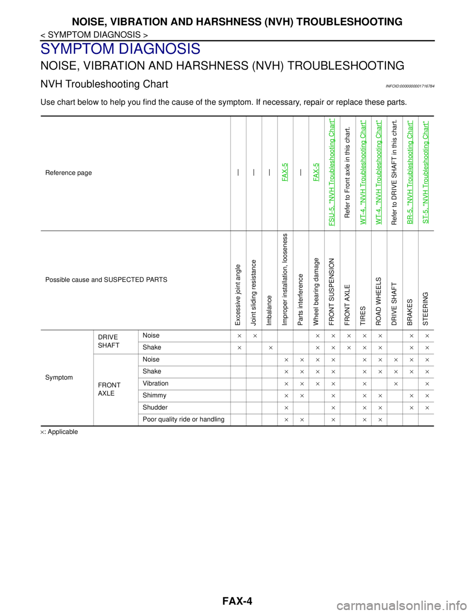
NVH Troubleshooting ChartINFOID:0000000001716784
Use chart below to help you find the cause of the symptom. If necessary, repair or replace these parts.
×: ApplicableReference page
—
—
—
FA X - 5—
FA X - 5
FSU-5, "
NVH Troubleshooting Chart
"
Refer to Front axle in this chart.
WT-4, "
NVH Troubleshooting Chart
"
WT-4, "
NVH Troubleshooting Chart
"
Refer to DRIVE SHAFT in this chart.
BR-5, "
NVH Troubleshooting Chart
"
ST-5, "
NVH Troubleshooting Chart
"
Possible cause and SUSPECTED PARTS
Excessive joint angle
Joint sliding resistance
Imbalance
Improper installation, looseness
Parts interference
Wheel bearing damage
FRONT SUSPENSION
FRONT AXLE
TIRES
ROAD WHEELS
DRIVE SHAFT
BRAKES
STEERING
SymptomDRIVE
SHAFTNoise×× ××××× ××
Shake× × ××××× ××
FRONT
AXLENoise×××× ×××××
Shake×××× ×××××
Vibration×××××××
Shimmy×××××××
Shudder× × ×× ××
Poor quality ride or handling×××××
Page 3181 of 5883

NOISE, VIBRATION AND HARSHNESS (NVH) TROUBLESHOOTING
FSU-5
< SYMPTOM DIAGNOSIS >
C
D
F
G
H
I
J
K
L
MA
B
FSU
N
O
P
SYMPTOM DIAGNOSIS
NOISE, VIBRATION AND HARSHNESS (NVH) TROUBLESHOOTING
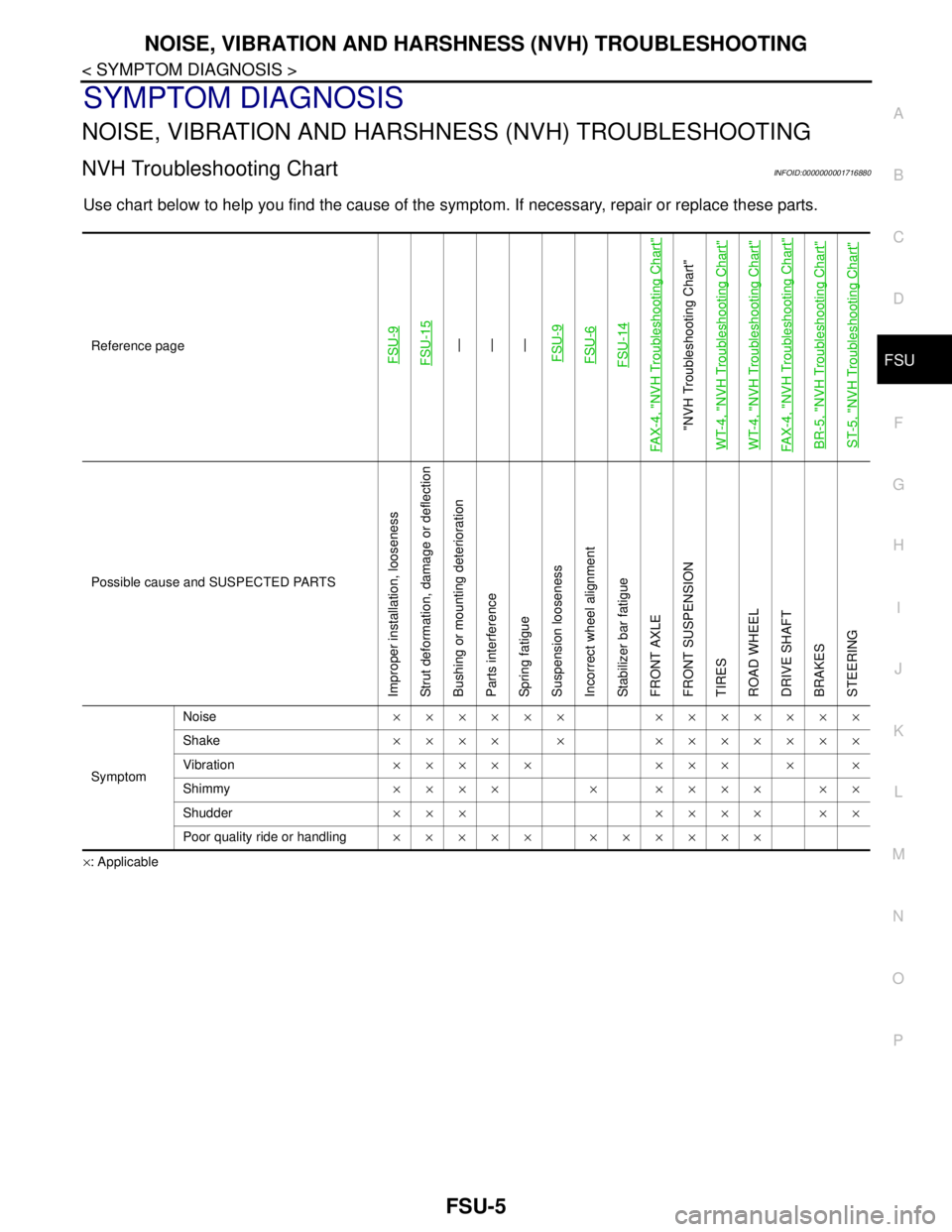
NVH Troubleshooting ChartINFOID:0000000001716880
Use chart below to help you find the cause of the symptom. If necessary, repair or replace these parts.
×: ApplicableReference page
FSU-9 FSU-15
—
—
—
FSU-9FSU-6FSU-14
FAX-4, "
NVH Troubleshooting Chart
"
"NVH Troubleshooting Chart"
WT-4, "
NVH Troubleshooting Chart
"
WT-4, "
NVH Troubleshooting Chart
"
FAX-4, "
NVH Troubleshooting Chart
"
BR-5, "
NVH Troubleshooting Chart
"
ST-5, "
NVH Troubleshooting Chart
"
Possible cause and SUSPECTED PARTS
Improper installation, looseness
Strut deformation, damage or deflection
Bushing or mounting deterioration
Parts interference
Spring fatigue
Suspension looseness
Incorrect wheel alignment
Stabilizer bar fatigue
FRONT AXLE
FRONT SUSPENSION
TIRES
ROAD WHEEL
DRIVE SHAFT
BRAKES
STEERING
SymptomNoise×××××× ×××××××
Shake×××× × ×××××××
Vibration××××× ××× × ×
Shimmy×××× × ×××× ××
Shudder××× ×××× ××
Poor quality ride or handling××××× ××××××
Page 4405 of 5883

PB-1
BRAKES
C
D
E
G
H
I
J
K
L
M
SECTION PB
A
B
PB
N
O
P
CONTENTS
PARKING BRAKE SYSTEM
PRECAUTION ...............................................2
PRECAUTIONS ...................................................2
Precaution for Supplemental Restraint System
(SRS) "AIR BAG" and "SEAT BELT PRE-TEN-
SIONER" ...................................................................
2
PREPARATION ............................................3
PREPARATION ...................................................3
Commercial Service Tool ..........................................3
ON-VEHICLE MAINTENANCE .....................4
PARKING BRAKE CONTROL ............................4
On-Vehicle Service ...................................................4
REMOVAL AND INSTALLATION ................5
PARKING BRAKE CONTROL ...........................5
Component ...............................................................5
Removal and Installation ..........................................5
PARKING BRAKE SHOE ..................................7
Exploded View ..........................................................7
Removal and Installation ..........................................7
Drum and Lining Break-in .........................................9
SERVICE DATA AND SPECIFICATIONS
(SDS) ............................................................
10
SERVICE DATA AND SPECIFICATIONS
(SDS) .................................................................
10
Parking Brake Control .............................................10
Parking Drum Brake ................................................10
Page 4411 of 5883
PARKING BRAKE SHOE
PB-7
< REMOVAL AND INSTALLATION >
C
D
E
G
H
I
J
K
L
MA
B
PB
N
O
P
PARKING BRAKE SHOE
Exploded ViewINFOID:0000000001724716
Removal and InstallationINFOID:0000000001724713
REMOVAL
WARNING:
Clean brakes with a vacuum dust collector to minimize the hazard of airborne particles or other mate-
rials.
1. Remove wheel and tire.
2. Remove the brake rotor with the parking brake lever completely disengaged. If the brake rotor cannot be
removed, remove as follows:
1. Anchor pin 2. Baffle plate 3. Lever
4. Brake Shoe 5. Spring 6. Strut
7. Retainer spring 8. Adjuster : Brake grease
AWFIA0083ZZ
Page 4412 of 5883

PB-8
< REMOVAL AND INSTALLATION >
PARKING BRAKE SHOE
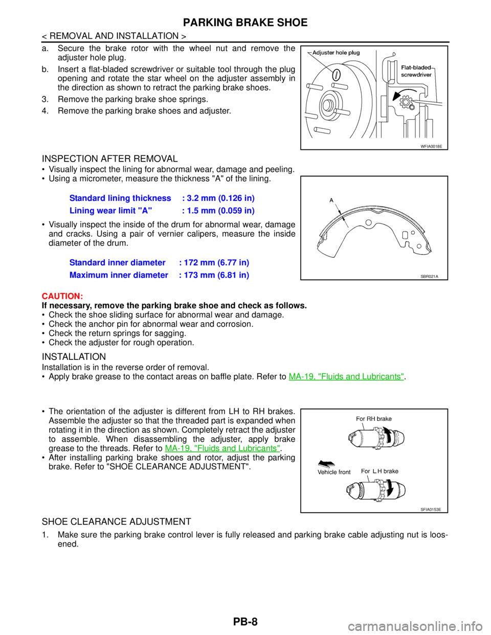
a. Secure the brake rotor with the wheel nut and remove the
adjuster hole plug.
b. Insert a flat-bladed screwdriver or suitable tool through the plug
opening and rotate the star wheel on the adjuster assembly in
the direction as shown to retract the parking brake shoes.
3. Remove the parking brake shoe springs.
4. Remove the parking brake shoes and adjuster.
INSPECTION AFTER REMOVAL
Visually inspect the lining for abnormal wear, damage and peeling.
Using a micrometer, measure the thickness "A" of the lining.
Visually inspect the inside of the drum for abnormal wear, damage
and cracks. Using a pair of vernier calipers, measure the inside
diameter of the drum.
CAUTION:
If necessary, remove the parking brake shoe and check as follows.
Check the shoe sliding surface for abnormal wear and damage.
Check the anchor pin for abnormal wear and corrosion.
Check the return springs for sagging.
Check the adjuster for rough operation.
INSTALLATION
Installation is in the reverse order of removal.
Apply brake grease to the contact areas on baffle plate. Refer to MA-19, "
Fluids and Lubricants".
The orientation of the adjuster is different from LH to RH brakes.
Assemble the adjuster so that the threaded part is expanded when
rotating it in the direction as shown. Completely retract the adjuster
to assemble. When disassembling the adjuster, apply brake
grease to the threads. Refer to MA-19, "
Fluids and Lubricants".
After installing parking brake shoes and rotor, adjust the parking
brake. Refer to "SHOE CLEARANCE ADJUSTMENT".
SHOE CLEARANCE ADJUSTMENT
1. Make sure the parking brake control lever is fully released and parking brake cable adjusting nut is loos-
ened.
WFIA0018E
Standard lining thickness : 3.2 mm (0.126 in)
Lining wear limit "A" : 1.5 mm (0.059 in)
Standard inner diameter : 172 mm (6.77 in)
Maximum inner diameter : 173 mm (6.81 in)
SBR021A
SFIA0153E
Page 4529 of 5883
RAX-2
< SYMPTOM DIAGNOSIS >
NOISE, VIBRATION AND HARSHNESS (NVH) TROUBLESHOOTING
SYMPTOM DIAGNOSIS
NOISE, VIBRATION AND HARSHNESS (NVH) TROUBLESHOOTING
NVH Troubleshooting ChartINFOID:0000000001724593
Use chart below to help you find the cause of the symptom. If necessary, repair or replace these parts.
×: ApplicableReference page
RAX-6—
RAX-5
RSU-2, "
NVH Troubleshooting Chart
"
WT-4, "
NVH Troubleshooting Chart
"
WT-4, "
NVH Troubleshooting Chart
"
BR-5, "
NVH Troubleshooting Chart
"
ST-5, "
NVH Troubleshooting Chart
"
Possible cause and SUSPECTED PARTS
Improper installation, looseness
Parts interference
Wheel bearing damage
REAR AXLE AND REAR SUSPENSION
TIRES
ROAD WHEEL
BRAKES
STEERING
Symptom REAR AXLENoise×× ×××××
Shake×× ×××××
Vibration×× ×× ×
Shimmy×× ×××××
Judder× ×××××
Poor quality ride or handling××××××
Page 4574 of 5883
RSU-2
< SYMPTOM DIAGNOSIS >
NOISE, VIBRATION AND HARSHNESS (NVH) TROUBLESHOOTING
SYMPTOM DIAGNOSIS
NOISE, VIBRATION AND HARSHNESS (NVH) TROUBLESHOOTING
NVH Troubleshooting ChartINFOID:0000000001724586
Use chart below to help you find the cause of the symptom. If necessary, repair or replace these parts.
×: ApplicableReference page
RSU-7RSU-8RSU-8RSU-8RSU-10RSU-7RSU-5
RAX-2, "
NVH Troubleshooting Chart
"
WT-4, "
NVH Troubleshooting Chart
"
WT-4, "
NVH Troubleshooting Chart
"
BR-5, "
NVH Troubleshooting Chart
"
ST-5, "
NVH Troubleshooting Chart
"
Possible cause and SUSPECTED PARTS
Improper installation, looseness
Shock absorber deformation, damage or deflection
Bushing or mounting deterioration
Parts interference
Spring fatigue
Suspension looseness
Incorrect wheel alignment
REAR AXLE
TIRES
ROAD WHEEL
BRAKES
STEERING
SymptomNoise×××××× ×××××
Shake×××× × ×××××
Vibration××××× ×× ×
Shimmy×××× ××××××
Judder ××× ×××××
Poor quality ride or handling××××× ××××
Page 4588 of 5883

SB-4
< BASIC INSPECTION >
INSPECTION
6. Repeat steps above as necessary to check the other seat belts.
SEAT BELT RETRACTOR ON-VEHICLE CHECK
Emergency Locking Retractors (ELR) and Automatic Locking Retractors (ALR)
NOTE:
All seat belt retractors are of the Emergency Locking Retractors (ELR) type. In an emergency (sudden stop)
the retractor will lock and prevent the webbing from extending any further. All 3-point type seat belt retractors
except the driver's seat belt also have an Automatic Locking Retractors (ALR) mode. The ALR mode (also
called child restraint mode) is used when installing child seats. The ALR mode is activated when the seat belt
is fully extended. When the webbing is then retracted partially, the ALR mode automatically locks the seat belt
in a specific position so the webbing cannot be extended any further. To cancel the ALR mode, allow the seat
belt to fully wind back into the retractor.
Check the seat belt retractors using the following test(s) to determine if a retractor assembly is operating prop-
erly.
ELR Function Stationary Check
Grasp the shoulder webbing and pull it forward quickly. The retractor should lock and prevent the belt from
extending further.
ALR Function Stationary Check
1. Pull out entire length of seat belt from retractor until a click is heard.
2. Retract the webbing partially. A clicking noise should be heard as the webbing retracts, indicating that the
retractor is in the Automatic Locking Retractors (ALR) mode.
3. Grasp the seat belt and try to pull out the retractor. The webbing must lock and not extend any further. If
NG, replace the retractor assembly.
4. Allow the entire length of the webbing to retract to cancel the automatic locking mode.
ELR Function Moving Check
WARNING:
Perform the following test in a safe, open area clear of other vehicles and obstructions (for example, a
large, empty parking lot). Road surface must be paved and dry. DO NOT perform the following test on
wet or gravel roads or on public streets and highways. This could result in an accident and serious
personal injury. The driver and passenger must be prepared to brace themselves in the event the
retractor does not lock.
1. Fasten driver's seat belt. Buckle a passenger into the seat for the belt that is to be tested.
2. Proceed to the designated safe area.
3. Drive the vehicle at approximately 16 km/h (10 MPH). Notify any passengers of a pending sudden stop
and the driver and passenger must be prepared to brace themselves in the event the retractor does not
lock, apply brakes firmly and make a very hard stop.
During the stop, seat belts should lock and not be extended. If the seat belt retractor assembly does not lock,
perform the retractor off-vehicle check.
SEAT BELT RETRACTOR OFF-VEHICLE CHECK
1. Remove the seat belt retractor. Refer to SB-6, "Removal and Installation of Front Seat Belt".