2007 NISSAN TIIDA Engine Mechanical
[x] Cancel search: Engine MechanicalPage 1371 of 5883
EC-22
< BASIC INSPECTION >[HR16DE (WITH EURO-OBD)]
INSPECTION AND ADJUSTMENT
INSPECTION AND ADJUSTMENT
BASIC INSPECTION
BASIC INSPECTION : Special Repair RequirementINFOID:0000000001161123
1.INSPECTION START
1. Check service records for any recent repairs that may indicate a related malfunction, or a current need for
scheduled maintenance.
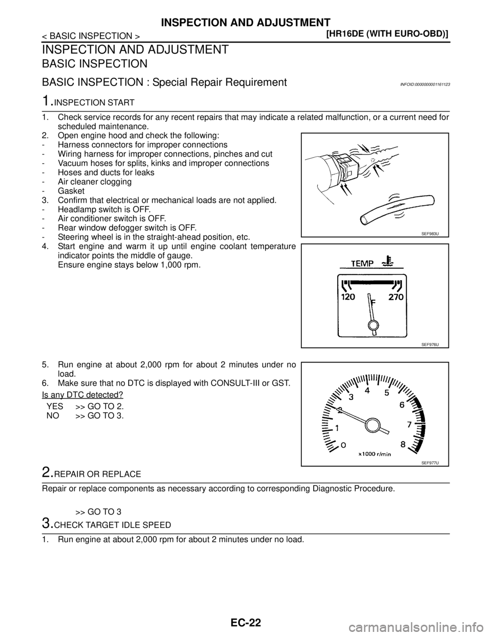
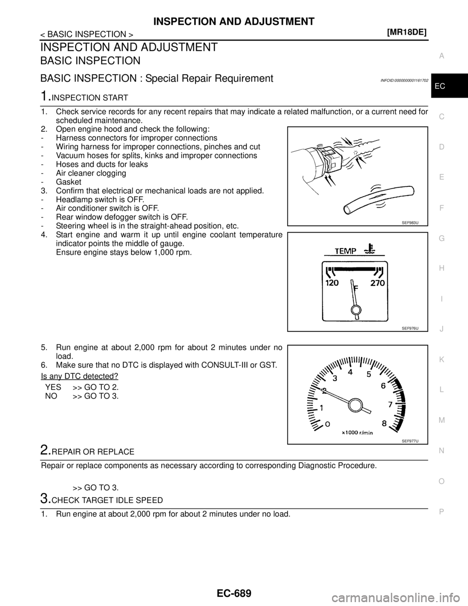
2. Open engine hood and check the following:
- Harness connectors for improper connections
- Wiring harness for improper connections, pinches and cut
- Vacuum hoses for splits, kinks and improper connections
- Hoses and ducts for leaks
- Air cleaner clogging
- Gasket
3. Confirm that electrical or mechanical loads are not applied.
- Headlamp switch is OFF.
- Air conditioner switch is OFF.
- Rear window defogger switch is OFF.
- Steering wheel is in the straight-ahead position, etc.
4. Start engine and warm it up until engine coolant temperature
indicator points the middle of gauge.
Ensure engine stays below 1,000 rpm.
5. Run engine at about 2,000 rpm for about 2 minutes under no
load.
6. Make sure that no DTC is displayed with CONSULT-III or GST.
Is any DTC detected?
YES >> GO TO 2.
NO >> GO TO 3.
2.REPAIR OR REPLACE
Repair or replace components as necessary according to corresponding Diagnostic Procedure.
>> GO TO 3
3.CHECK TARGET IDLE SPEED
1. Run engine at about 2,000 rpm for about 2 minutes under no load.
SEF983U
SEF976U
SEF977U
Page 1716 of 5883
ENGINE CONTROL SYSTEM SYMPTOMS
EC-367
< SYMPTOM DIAGNOSIS >[HR16DE (WITH EURO-OBD)]
C
D
E
F
G
H
I
J
K
L
MA
EC
N
P O
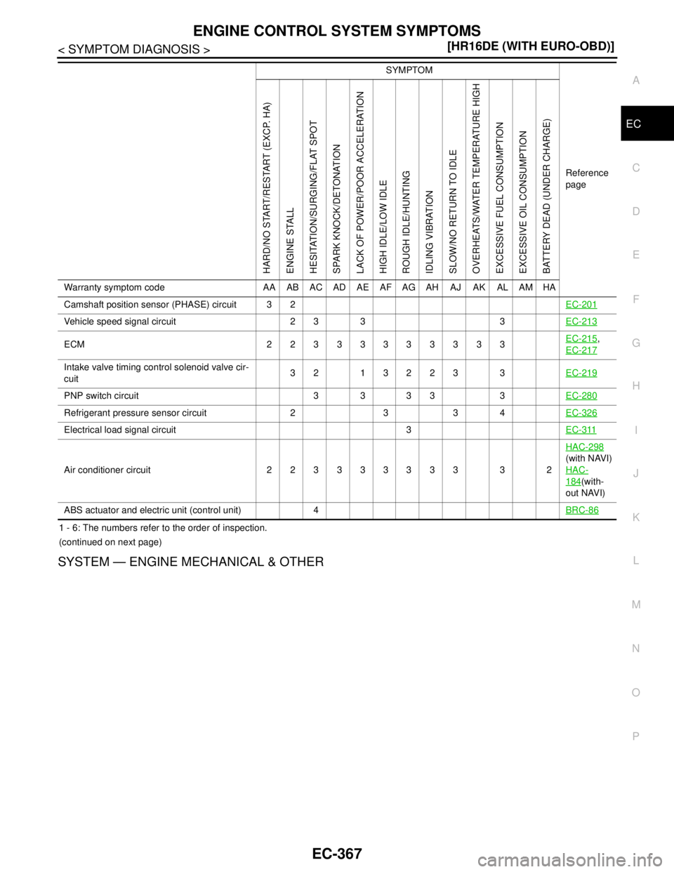
1 - 6: The numbers refer to the order of inspection.
(continued on next page)
SYSTEM — ENGINE MECHANICAL & OTHER
Camshaft position sensor (PHASE) circuit 3 2EC-201
Vehicle speed signal circuit 2 3 3 3EC-213
ECM 22333333333EC-215,
EC-217
Intake valve timing control solenoid valve cir-
cuit32 13223 3EC-219
PNP switch circuit 3 3 3 3 3EC-280
Refrigerant pressure sensor circuit 2 3 3 4EC-326
Electrical load signal circuit 3EC-311
Air conditioner circuit 223333333 3 2HAC-298
(with NAVI)
HAC-
184(with-
out NAVI)
ABS actuator and electric unit (control unit) 4BRC-86
SYMPTOM
Reference
page
HARD/NO START/RESTART (EXCP. HA)
ENGINE STALL
HESITATION/SURGING/FLAT SPOT
SPARK KNOCK/DETONATION
LACK OF POWER/POOR ACCELERATION
HIGH IDLE/LOW IDLE
ROUGH IDLE/HUNTING
IDLING VIBRATION
SLOW/NO RETURN TO IDLE
OVERHEATS/WATER TEMPERATURE HIGH
EXCESSIVE FUEL CONSUMPTION
EXCESSIVE OIL CONSUMPTION
BATTERY DEAD (UNDER CHARGE)
Warranty symptom code AA AB AC AD AE AF AG AH AJ AK AL AM HA
Page 1734 of 5883
INSPECTION AND ADJUSTMENT
EC-385
< BASIC INSPECTION >[HR16DE (WITHOUT EURO-OBD)]
C
D
E
F
G
H
I
J
K
L
MA
EC
N
P O
INSPECTION AND ADJUSTMENT
BASIC INSPECTION
BASIC INSPECTION : Special Repair RequirementINFOID:0000000001161429
1.INSPECTION START
1. Check service records for any recent repairs that may indicate a related malfunction, or a current need for
scheduled maintenance.
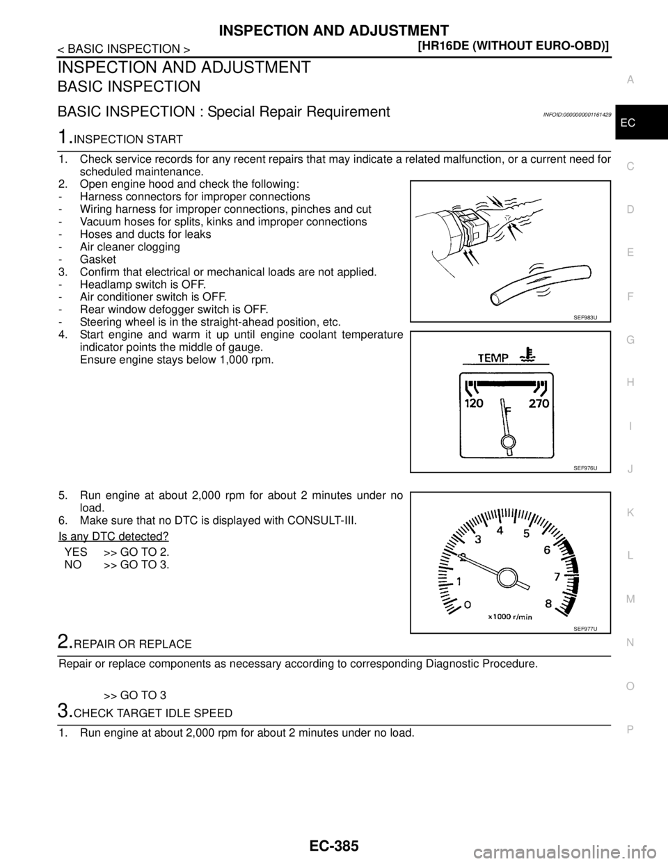
2. Open engine hood and check the following:
- Harness connectors for improper connections
- Wiring harness for improper connections, pinches and cut
- Vacuum hoses for splits, kinks and improper connections
- Hoses and ducts for leaks
- Air cleaner clogging
- Gasket
3. Confirm that electrical or mechanical loads are not applied.
- Headlamp switch is OFF.
- Air conditioner switch is OFF.
- Rear window defogger switch is OFF.
- Steering wheel is in the straight-ahead position, etc.
4. Start engine and warm it up until engine coolant temperature
indicator points the middle of gauge.
Ensure engine stays below 1,000 rpm.
5. Run engine at about 2,000 rpm for about 2 minutes under no
load.
6. Make sure that no DTC is displayed with CONSULT-III.
Is any DTC detected?
YES >> GO TO 2.
NO >> GO TO 3.
2.REPAIR OR REPLACE
Repair or replace components as necessary according to corresponding Diagnostic Procedure.
>> GO TO 3
3.CHECK TARGET IDLE SPEED
1. Run engine at about 2,000 rpm for about 2 minutes under no load.
SEF983U
SEF976U
SEF977U
Page 2020 of 5883
ENGINE CONTROL SYSTEM SYMPTOMS
EC-671
< SYMPTOM DIAGNOSIS >[HR16DE (WITHOUT EURO-OBD)]
C
D
E
F
G
H
I
J
K
L
MA
EC
N
P O
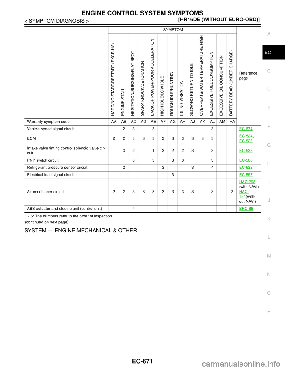
1 - 6: The numbers refer to the order of inspection.
(continued on next page)
SYSTEM — ENGINE MECHANICAL & OTHER
Vehicle speed signal circuit 2 3 3 3EC-634
ECM 22333333333EC-524,
EC-526
Intake valve timing control solenoid valve cir-
cuit32 13223 3EC-528
PNP switch circuit 3 3 3 3 3EC-566
Refrigerant pressure sensor circuit 2 3 3 4EC-632
Electrical load signal circuit 3EC-597
Air conditioner circuit 223333333 3 2HAC-298
(with NAVI)
HAC-
184(with-
out NAVI)
ABS actuator and electric unit (control unit) 4BRC-86
SYMPTOM
Reference
page
HARD/NO START/RESTART (EXCP. HA)
ENGINE STALL
HESITATION/SURGING/FLAT SPOT
SPARK KNOCK/DETONATION
LACK OF POWER/POOR ACCELERATION
HIGH IDLE/LOW IDLE
ROUGH IDLE/HUNTING
IDLING VIBRATION
SLOW/NO RETURN TO IDLE
OVERHEATS/WATER TEMPERATURE HIGH
EXCESSIVE FUEL CONSUMPTION
EXCESSIVE OIL CONSUMPTION
BATTERY DEAD (UNDER CHARGE)
Warranty symptom code AA AB AC AD AE AF AG AH AJ AK AL AM HA
Page 2038 of 5883
INSPECTION AND ADJUSTMENT
EC-689
< BASIC INSPECTION >[MR18DE]
C
D
E
F
G
H
I
J
K
L
MA
EC
N
P O
INSPECTION AND ADJUSTMENT
BASIC INSPECTION
BASIC INSPECTION : Special Repair RequirementINFOID:0000000001161702
1.INSPECTION START
1. Check service records for any recent repairs that may indicate a related malfunction, or a current need for
scheduled maintenance.
2. Open engine hood and check the following:
- Harness connectors for improper connections
- Wiring harness for improper connections, pinches and cut
- Vacuum hoses for splits, kinks and improper connections
- Hoses and ducts for leaks
- Air cleaner clogging
- Gasket
3. Confirm that electrical or mechanical loads are not applied.
- Headlamp switch is OFF.
- Air conditioner switch is OFF.
- Rear window defogger switch is OFF.
- Steering wheel is in the straight-ahead position, etc.
4. Start engine and warm it up until engine coolant temperature
indicator points the middle of gauge.
Ensure engine stays below 1,000 rpm.
5. Run engine at about 2,000 rpm for about 2 minutes under no
load.
6. Make sure that no DTC is displayed with CONSULT-III or GST.
Is any DTC detected?
YES >> GO TO 2.
NO >> GO TO 3.
2.REPAIR OR REPLACE
Repair or replace components as necessary according to corresponding Diagnostic Procedure.
>> GO TO 3.
3.CHECK TARGET IDLE SPEED
1. Run engine at about 2,000 rpm for about 2 minutes under no load.
SEF983U
SEF976U
SEF977U
Page 2374 of 5883
ENGINE CONTROL SYSTEM
EC-1025
< SYMPTOM DIAGNOSIS >[MR18DE]
C
D
E
F
G
H
I
J
K
L
MA
EC
N
P O
1 - 6: The numbers refer to the order of inspection.
(continued on next page)
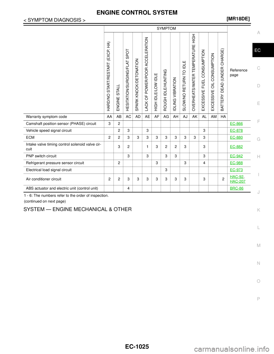
SYSTEM — ENGINE MECHANICAL & OTHER
Camshaft position sensor (PHASE) circuit 3 2EC-866
Vehicle speed signal circuit 2 3 3 3EC-878
ECM 22333333333EC-880
Intake valve timing control solenoid valve cir-
cuit32 13223 3EC-882
PNP switch circuit 3 3 3 3 3EC-942
Refrigerant pressure sensor circuit 2 3 3 4EC-988
Electrical load signal circuit 3EC-973
Air conditioner circuit 223333333 3 2HAC-92,
HAC-207
ABS actuator and electric unit (control unit) 4BRC-86
SYMPTOM
Reference
page
HARD/NO START/RESTART (EXCP. HA)
ENGINE STALL
HESITATION/SURGING/FLAT SPOT
SPARK KNOCK/DETONATION
LACK OF POWER/POOR ACCELERATION
HIGH IDLE/LOW IDLE
ROUGH IDLE/HUNTING
IDLING VIBRATION
SLOW/NO RETURN TO IDLE
OVERHEATS/WATER TEMPERATURE HIGH
EXCESSIVE FUEL CONSUMPTION
EXCESSIVE OIL CONSUMPTION
BATTERY DEAD (UNDER CHARGE)
Warranty symptom code AA AB AC AD AE AF AG AH AJ AK AL AM HA
Page 2397 of 5883
EC-1048
< BASIC INSPECTION >[K9K]
INSPECTION AND ADJUSTMENT
>>INSPECTION END
BASIC INSPECTION : Special Repair Requirement (TEST 5: Rail High Pressure Reg-
ulation Check)
INFOID:0000000001162519
NOTE:
If contaminants (swarf) can be seen in the transparent return pipe, the entire fuel injection system (fuel injec-
tors, pump, rail, high pressure pipes and all return pipes) must be replaced.
CONDITIONS PRIOR TO TEST
- Engine coolant temperature between 80 - 90°C (176 - 194°F).
- All the electrical load are switched off.
- Air conditioning is switched off.
- The tank is at least half-full.
- The pipe connections and unions have been checked.
- Check the sealing of the high pressure pipes and unions.
CAUSE
- Rail pressure variations around the setpoint.
- The rail reference pressure is not reached.
- Rough idle.
- Possibly noisy combustion.
1.CHECK AIR BUBBLES
1. Start engine
2. Are there large air bubbles in the transparent supply pipe going to the pump?
Is the inspection result normal?
YES >> Check low pressure system.
NO >> GO TO 2.
2.CHECK HIGH PRESSURE SUPPLY PUMP (VOLUMETRIC CONTROL VALVE)-I
Disconnect high pressure supply pump (volumetric control valve) harness connector.
Does the engine stop?
YES >> GO TO 3.
NO >> Replace high pressure supply pump (the high pressure supply pump [volumetric control valve]
remains open mechanically).
3.CHECK HIGH PRESSURE SUPPLY PUMP (PRESSURE CONTROL VALVE)-I
1. Reconnect high pressure supply pump (volumetric control valve) harness connector.
2. Turn ignition switch OFF and wait at least 30 seconds.
3. Start engine.
4. Disconnect high pressure supply pump (pressure control valve) harness connector.
Does the engine stop?
YES >> GO TO 4.
NO >> Replace high pressure supply pump (the high pressure supply pump [pressure control valve]
remains open mechanically).
4.CHECK FUEL INJECTOR
1. Reconnect high pressure supply pump (pressure control valve) harness connector.
2. Wait at least 30 seconds.
3. Start engine and let it idle speed.
4. Select “DATA MONITOR” mode with CONSULT-III.
5. Check that the “F/FLOW CORR CYL1”, “F/FLOW CORR CYL2”, “F/FLOW CORR CYL3”, “F/FLOW
CORR CYL4” indication.
Are the reference value 0.3 - 1.9?
YES >> GO TO 6.
NO >> GO TO 5.
5.CHECK MAJOR LEAK IN FUEL INJECTOR/FUEL INJECTORS OPEN
Carry out TEST 6.
Page 2648 of 5883
EM-1
ENGINE
C
D
E
F
G
H
I
J
K
L
M
SECTION EM
A
EM
N
O
P
CONTENTS
ENGINE MECHANICAL
HR16DE
SYMPTOM DIAGNOSIS ...............................
5
NOISE, VIBRATION AND HARSHNESS
(NVH) TROUBLESHOOTING .............................
5
NVH Troubleshooting - Engine Noise .......................5
Use the Chart Below to Help You Find the Cause
of the Symptom .........................................................
6
PRECAUTION ...............................................7
PRECAUTIONS ...................................................7
Precaution for Supplemental Restraint System
(SRS) "AIR BAG" and "SEAT BELT PRE-TEN-
SIONER" ...................................................................
7
Precaution for Procedure without Cowl Top Cover ......7
Precaution Necessary for Steering Wheel Rota-
tion After Battery Disconnect .....................................
7
Precaution for Drain Coolant .....................................8
Precaution for Disconnecting Fuel Piping .................8
Precaution for Removal and Disassembly ................8
Precaution for Inspection, Repair and Replace-
ment ..........................................................................
8
Precaution for Assembly and Installation ..................8
Parts Requiring Angular Tightening ..........................8
Precaution for Liquid Gasket .....................................9
PREPARATION ...........................................11
PREPARATION ..................................................11
Special Service Tools ..............................................11
Commercial Service Tools ......................................12
ON-VEHICLE MAINTENANCE ....................15
DRIVE BELTS ....................................................15
Checking .................................................................15
Tension Adjustment ................................................15
Removal and Installation .........................................16
AIR CLEANER FILTER ......................................18
Removal and Installation .........................................18
SPARK PLUG ...................................................19
Exploded View .........................................................19
Removal and Installation .........................................19
CAMSHAFT VALVE CLEARANCE ..................21
Inspection and Adjustment ......................................21
COMPRESSION PRESSURE ...........................24
Inspection ................................................................24
ON-VEHICLE REPAIR .................................25
DRIVE BELT IDLER PULLEY ..........................25
Exploded View .........................................................25
Removal and Installation .........................................25
AIR CLEANER AND AIR DUCT .......................27
Exploded View .........................................................27
Removal and Installation .........................................27
Inspection ................................................................28
INTAKE MANIFOLD .........................................29
Exploded View .........................................................29
Removal and Installation .........................................29
EXHAUST MANIFOLD ......................................32
Exploded View .........................................................32
Removal and Installation .........................................32
FUEL INJECTOR AND FUEL TUBE ................35
Exploded View .........................................................35
Removal and Installation .........................................35
Inspection ................................................................39
OIL PAN (LOWER) ...........................................40
Exploded View .........................................................40
Removal and Installation .........................................40
Inspection ................................................................41
OIL PAN (UPPER) AND OIL STRAINER .........42
Component ..............................................................42