2007 NISSAN TIIDA Engine Mechanical
[x] Cancel search: Engine MechanicalPage 3245 of 5883
SERVICE INFORMATION FOR ELECTRICAL INCIDENT
GI-51
< BASIC INSPECTION >
C
D
E
F
G
H
I
J
K
L
MB
GI
N
O
PBASIC INSPECTION
SERVICE INFORMATION FOR ELECTRICAL INCIDENT
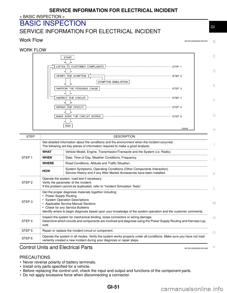
Work FlowINFOID:0000000001691467
WORK FLOW
Control Units and Electrical PartsINFOID:0000000001691468
PRECAUTIONS
Never reverse polarity of battery terminals.
Install only parts specified for a vehicle.
Before replacing the control unit, check the input and output and functions of the component parts.
Do not apply excessive force when disconnecting a connector.
SGI838
STEP DESCRIPTION
STEP 1Get detailed information about the conditions and the environment when the incident occurred.
The following are key pieces of information required to make a good analysis:
WHATVehicle Model, Engine, Transmission/Transaxle and the System (i.e. Radio).
WHENDate, Time of Day, Weather Conditions, Frequency.
WHERERoad Conditions, Altitude and Traffic Situation.
HOWSystem Symptoms, Operating Conditions (Other Components Interaction).
Service History and if any After Market Accessories have been installed.
STEP 2Operate the system, road test if necessary.
Verify the parameter of the incident.
If the problem cannot be duplicated, refer to “Incident Simulation Tests”.
STEP 3Get the proper diagnosis materials together including:
Power Supply Routing
System Operation Descriptions
Applicable Service Manual Sections
Check for any Service Bulletins
Identify where to begin diagnosis based upon your knowledge of the system operation and the customer comments.
STEP 4Inspect the system for mechanical binding, loose connectors or wiring damage.
Determine which circuits and components are involved and diagnose using the Power Supply Routing and Harness Lay-
outs.
STEP 5 Repair or replace the incident circuit or component.
STEP 6Operate the system in all modes. Verify the system works properly under all conditions. Make sure you have not inad-
vertently created a new incident during your diagnosis or repair steps.
Page 4363 of 5883
MWI-56
< ECU DIAGNOSIS >
BCM (BODY CONTROL MODULE)
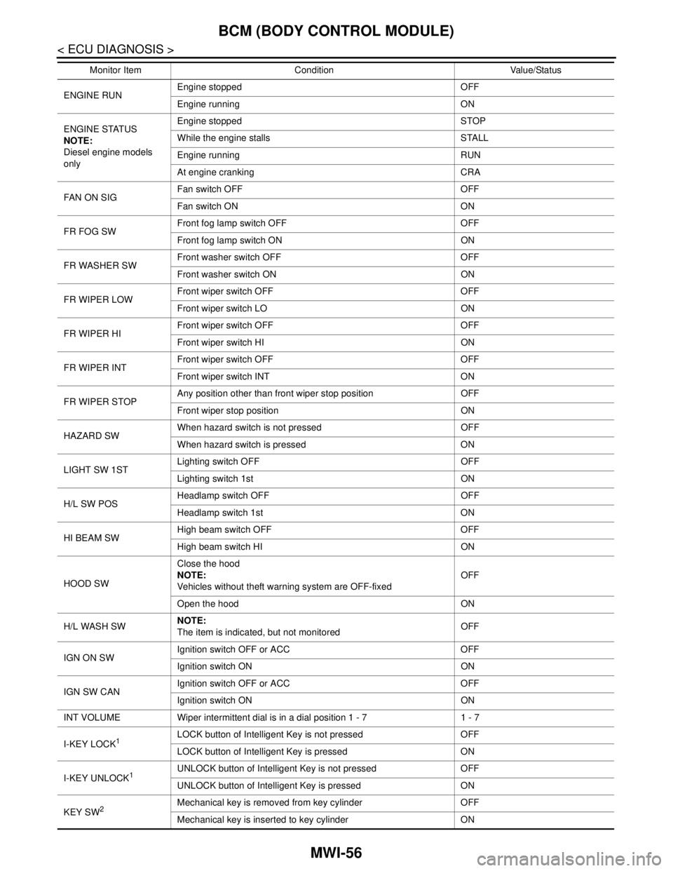
ENGINE RUNEngine stopped OFF
Engine running ON
ENGINE STATUS
NOTE:
Diesel engine models
onlyEngine stopped STOP
While the engine stalls STALL
Engine running RUN
At engine cranking CRA
FA N O N S I GFan switch OFF OFF
Fan switch ON ON
FR FOG SWFront fog lamp switch OFF OFF
Front fog lamp switch ON ON
FR WASHER SWFront washer switch OFF OFF
Front washer switch ON ON
FR WIPER LOWFront wiper switch OFF OFF
Front wiper switch LO ON
FR WIPER HIFront wiper switch OFF OFF
Front wiper switch HI ON
FR WIPER INTFront wiper switch OFF OFF
Front wiper switch INT ON
FR WIPER STOPAny position other than front wiper stop position OFF
Front wiper stop position ON
HAZARD SWWhen hazard switch is not pressed OFF
When hazard switch is pressed ON
LIGHT SW 1STLighting switch OFF OFF
Lighting switch 1st ON
H/L SW POSHeadlamp switch OFF OFF
Headlamp switch 1st ON
HI BEAM SWHigh beam switch OFF OFF
High beam switch HI ON
HOOD SWClose the hood
NOTE:
Vehicles without theft warning system are OFF-fixedOFF
Open the hood ON
H/L WASH SWNOTE:
The item is indicated, but not monitoredOFF
IGN ON SWIgnition switch OFF or ACC OFF
Ignition switch ON ON
IGN SW CANIgnition switch OFF or ACC OFF
Ignition switch ON ON
INT VOLUME Wiper intermittent dial is in a dial position 1 - 7 1 - 7
I-KEY LOCK
1LOCK button of Intelligent Key is not pressed OFF
LOCK button of Intelligent Key is pressed ON
I-KEY UNLOCK
1UNLOCK button of Intelligent Key is not pressed OFF
UNLOCK button of Intelligent Key is pressed ON
KEY SW
2Mechanical key is removed from key cylinder OFF
Mechanical key is inserted to key cylinder ON Monitor Item Condition Value/Status
Page 4633 of 5883

SEC-8
< FUNCTION DIAGNOSIS >[WITH INTELLIGENT KEY SYSTEM]
INTELLIGENT KEY SYSTEM/ENGINE START FUNCTION
FUNCTION DIAGNOSIS
INTELLIGENT KEY SYSTEM/ENGINE START FUNCTION
System DiagramINFOID:0000000001404034
System DescriptionINFOID:0000000001404035
INPUT/OUTPUT SIGNAL CHART
Intelligent Key Unit
IPDM E/R
BCM
SYSTEM DESCRIPTION
The engine start function of Intelligent Key system is a system that makes it possible to start and stop the
engine without using the key. It verifies the electronic ID using two-way communications when pressing the
ignition knob switch while carrying the Intelligent Key, which operates based on the results of electronic ID
verification for Intelligent Key using two-way communications between the Intelligent Key and the vehicle.
NOTE:
The driver should carry the Intelligent Key at all times.
Switch/Input signalInput signal to
Intelligent Key unit Intelligent Key unit
functionActuator/Output signal
Key switchMechanical key
(insert/remove)
Engine start function KEY warning lamp/buzzer
Steering lock unit
Starter relay request (to IPDM E/
R)
Inside key antenna
(Instrument center, console, rear
seat)
Key interlock solenoid Ignition knob switchIgnition knob
(push/release)
Steering lock unitSteering lock
(lock/unlock)
Inside key antenna
(Instrument center, console, rear
seat)Intelligent key
(inside antenna detection
area or not.)
Switch/Input signalInput signal to
IPDM E/R IPDM E/R function Actuator/Output signal
Park/neutral position switch (only
for A/T models)P,N range Engine start function Starter relay
Starter motor
Switch/Input signalInput signal to
BCM BCM function Actuator/Output signal
Key switchMechanical key
(insert/remove)Engine start function Inside key antenna
(Instrument center, console, rear
seat)
MIIB0785E
Page 4634 of 5883

INTELLIGENT KEY SYSTEM/ENGINE START FUNCTION
SEC-9
< FUNCTION DIAGNOSIS >[WITH INTELLIGENT KEY SYSTEM]
C
D
E
F
G
H
I
J
L
MA
B
SEC
N
O
P
Intelligent Key has 2 IDs (for Intelligent Key and for NATS). It can perform the door lock/unlock operation and
the engine start operation when the registered Intelligent Key is carried.
When the Intelligent Key battery is discharged, it can be used as emergency back-up by inserting the
mechanical key set in the Intelligent Key to the ignition key cylinder. At that time, perform the NATS ID verifi-
cation. If it is used when the Intelligent Key is carried, perform the Intelligent Key ID verification.
If the ID is successfully verified, and when the ignition knob switch is pressed, steering lock will be released
and initiating the engine will be possible.
The door lock/unlock operation can be performed when the Intelligent Key battery is discharged, by operat-
ing the driver door key cylinder using the mechanical key set in the Intelligent Key.
Up to 4 Intelligent Keys can be registered (including the standard Intelligent Key) on request from the owner.
NOTE:
Refer to XX-XX, "*****"
for any functions other than engine start function of Intelligent Key system.
PRECAUTIONS FOR INTELLIGENT KEY SYSTEM
In the Intelligent Key system, the transponder [the chip for NATS ID verification] is integrated into the
Intelligent Key. (For non-Intelligent Key systems, it is integrated into the mechanical key.) Therefore,
the mechanical key cannot perform the ID verification, and thus it cannot start the engine. Instead,
the NATS ID verification can be performed by inserting the mechanical key into the key cylinder, and
then it can start the engine.
OPERATION WHEN INTELLIGENT KEY IS CARRIED
1. When the ignition knob switch and brake switch are ON, and Intelligent Key unit is transmitting the request
signal to the Intelligent Key.
2. The Intelligent Key receives the request signal and transmits the Intelligent Key ID signal to the Intelligent
Key unit.
3. The Intelligent Key unit receives the Intelligent Key ID signal and verifies it with the registered ID.
4. Intelligent Key unit transmits the steering lock unlock signal to steering lock unit and turn on the key warn-
ing lamp (green) if the verification results are OK. (The detail of key warning lamp operation, refer to XX-
XX, "*****")
5. Release of the steering lock.
6. BCM transmits the starter request signal via CAN communication to IPDM E/R and turns the starter relay
in IPDM E/R ON if BCM judges that the engine start condition is satisfied.
7. IPDM E/R turns the starter control relay ON when receiving the starter request signal.
8. When shift position is in P or N position, battery power is supplied through the starter relay and operate
the starter motor and to start the cranking.
CAUTION:
If a malfunction is detected in the Intelligent Key system, the “KEY” warning lamp in the combina-
tion meter illuminates. At that time, the engine cannot be started.
OPERATION RANGE
Engine can be started when Intelligent Key is inside the vehicle. However, sometimes engine might not start
when Intelligent Key is on instrument panel or in glove box.
OPERATION WHEN MECHANICAL KEY IS USED
When the Intelligent Key battery is discharged, performs the NATS ID verification between the integrated tran-
sponder and BCM by inserting the mechanical key into the key cylinder, and then the engine can be started.
For details relating to starting the engine using mechanical key, refer to SEC-12, "
System Description".
STEERING LOCK OPERATION
Steering is locked by steering lock unit when ignition switch is in the OFF position (the ignition knob is
released) and key switch is OFF (key is removed from ignition key cylinder).
KEY INTERLOCK OPERATION (ONLY FOR M/T MODELS)
In case of a M/T vehicle is in motion and ignition is turned into LOCK position, steering lock unit causes a risk
by activating the steering lock actuator. The key interlock operation is designed to override the steering lock
system and prevent the situation mentioned above from occuring.
LOCK condition
When the following conditions are fulfilled, key interlock solenoid will be locked. (Steering lock inactive)
1 second passes after ignition switch is in ON position and engine revolution speed goes above 500 rpm.
UNLOCK condition
Page 4637 of 5883

SEC-12
< FUNCTION DIAGNOSIS >[WITH INTELLIGENT KEY SYSTEM]
NATS (NISSAN ANTI-THEFT SYSTEM)
NATS (NISSAN ANTI-THEFT SYSTEM)
System DiagramINFOID:0000000001404038
System DescriptionINFOID:0000000001404039
INPUT/OUTPUT SIGNAL CHART
Intelligent Key Unit
BCM
SYSTEM DESCRIPTION
NATS (Nissan Anti-Theft System) has the following immobilizer functions:
Engine immobilizer shows high anti-theft performance to prevent engine from starting by other than the
owner.
Only a key with key ID registered in BCM and ECM can start engine, and shows high anti-theft performance
to prevent key from being copied or stolen.
Security indicator always flashes with mechanical key removed condition (key switch: OFF) and ignition
knob released condition on LOCK position (ignition knob switch: OFF).
Therefore, NATS warns outsiders that the vehicle is equipped with the anti-theft system. Refer to XX-XX,
"*****".
If system detects malfunction, security indicator illuminates when ignition switch is turned to ON position.
If the owner requires, ignition key ID or mechanical key ID can be registered for up to 4 keys.
During trouble diagnosis or when the following parts have been replaced, and if mechanical key is added,
registration* is required.
*1: All keys kept by the owner of the vehicle should be registered with mechanical key.
-ECM
-BCM
LIIA2537E
Switch/Input signal Input signal to BCM BCM function Actuator/Output signal
Ignition knob switchIgnition knob
(push/release)
NATS Steering lock unit Key switchMechanical key
(Insert/remove)
Steering lock unitSteering
(lock/unlock)
ECM Engine status signal
Switch/Input signal Input signal to BCM BCM function Actuator/Output signal
NATS antenna amp. Key ID
NATS Security indicator lamp
Starter request
ECM Engine status signal
Page 4638 of 5883

NATS (NISSAN ANTI-THEFT SYSTEM)
SEC-13
< FUNCTION DIAGNOSIS >[WITH INTELLIGENT KEY SYSTEM]
C
D
E
F
G
H
I
J
L
MA
B
SEC
N
O
P
- Mechanical key
- ABS actuator control unit
- EPS control unit
- IPDM E/R
NATS trouble diagnosis, system initialization and additional registration of other mechanical key IDs must be
carried out using CONSULT-III hardware and SECURITY CARD.
When NATS initialization has been completed, the ID of the inserted mechanical key or mechanical key IDs
can be carried out.
Possible symptom of NATS malfunction is “Engine cannot start”. In C11, the engine can be started with the
Intelligent Key system and NATS. Identify the possible causes according to “Work Flow”, Refer to SEC-4,
"Work Flow".
If ECM other than Genuine NISSAN is installed, the engine cannot be started. For ECM replacement proce-
dure, refer to SEC-7, "
ECM RE-COMMUNICATING FUNCTION : Description".
PRECAUTIONS FOR KEY REGISTRATION
The key registration is a procedure that erases the current NATS ID once, and then re-registers a new ID.
Therefore the registered Intelligent Key is necessary for this procedure. Before starting the registration oper-
ation collect all registered Intelligent Keys from the customer.
The NATS ID registration is the procedure that registers the ID stored into the transponder (integrated in
mechanical key) to BCM.
The Intelligent Key ID registration is the procedure that registers the ID to Intelligent Key unit.
When performing the Intelligent Key system registration only, the engine cannot be started by inserting the
key into the key cylinder. When performing the NATS registration only, the engine cannot be started by using
the mechanical key.
SECURITY INDICATOR
Always flashes with ignition knob released (ignition knob switch: OFF) condition on ignition knob LOCK posi-
tion.
Always flashes with ignition knob released (ignition knob switch: OFF) condition on mechanical key removed
position.
Turns ON steady when the NATS is activated.
MAINTENANCE INFORMATION
CAUTION:
It is necessary to perform NATS ID registration when replacing any of the following part.
If it's not (or fail to do so), the electrical system may not operate properly.
BCM
ECM
Intelligent Key unit
Intelligent Key
IPDM E/R
NATS antenna amp.
Page 4651 of 5883

SEC-26
< COMPONENT DIAGNOSIS >[WITH INTELLIGENT KEY SYSTEM]
B2190, P1614 NATS ANTENNA AMP.
B2190, P1614 NATS ANTENNA AMP.
DescriptionINFOID:0000000001404060
Performs ID verification through BCM and NATS antenna amplifier when ignition knob switch is pressed.
Prohibits the release of steering lock or start of engine when an unregistered ID of mechanical key is used.
DTC LogicINFOID:0000000001404061
DTC DETECTION LOGIC
DTC CONFIRMATION PROCEDURE
1.PERFORM DTC CONFIRMATION PROCEDURE
1. Insert mechanical key into the key cylinder.
2. Press the ignition knob switch.
3. Check “Self diagnostic result” with CONSULT-III.
Is DTC detected?
YES >> Refer to XX-XX, "*****".
NO >> INSPECTION END.
Diagnosis ProcedureINFOID:0000000001532029
1.CHECK NATS ANTENNA AMP. INSTALLATION
Check NATS antenna amp. installation. Refer to XX-XX, "*****"
.
Is the inspection result normal?
YES >> GO TO 2.
NO >> Reinstall NATS antenna amp. correctly.
2.CHECK NVIS (NATS) IGNITION KEY ID CHIP
Start engine with another registered NATS ignition key.
Does the engine start?
YES >> Ignition key ID chip is malfunctioning.
Replace the ignition key.
Perform initialization with CONSULT-III.
For initialization, refer to “CONSULT-III Operation Manual”.
NO >> GO TO 3.
3.CHECK POWER SUPPLY FOR NATS ANTENNA AMP.
1. Turn ignition switch OFF.
2. Check voltage between NATS antenna amp. connector M21 terminal 1 and ground.
DTC No.Trouble diagnosis
nameDTC detecting condition Possible cause
B2190
NATS ANTENNA
AMP Inactive communication between NATS antenna
amp. and BCM.
Mechanical key is malfunctioning. Harness or connectors
(The NATS antenna amp. circuit is
open or shorted)
Mechanical key
NATS antenna amp.
BCM P1614
Page 4654 of 5883

B2191, P1615 DIFFERENCE OF KEY
SEC-29
< COMPONENT DIAGNOSIS >[WITH INTELLIGENT KEY SYSTEM]
C
D
E
F
G
H
I
J
L
MA
B
SEC
N
O
P
B2191, P1615 DIFFERENCE OF KEY
DescriptionINFOID:0000000001404063
Performs ID verification through BCM when ignition knob switch is pressed.
Prohibits the release of steering lock or start of engine when an unregistered ID of mechanical key is used.
DTC LogicINFOID:0000000001404064
DTC DETECTION LOGIC
DTC CONFIRMATION PROCEDURE
1.PERFORM DTC CONFIRMATION PROCEDURE
1. Insert mechanical key into the key cylinder.
2. Press the ignition knob switch.
3. Check “Self diagnostic result” with CONSULT-III.
Is DTC detected?
YES >> Refer toSEC-29, "Diagnosis Procedure".
NO >> INSPECTION END.
Diagnosis ProcedureINFOID:0000000001404065
1.PERFORM INITIALIZATION
Perform initialization with CONSULT-III. Re-register all mechanical keys.
For initialization and registration of mechanical key. Refer to CONSULT-III Operation Manual.
Can the system be initialized and can the engine be started with re-registered mechanical key?
YES >> Mechanical key was unregistered.
NO >> BCM is malfunctioning.
Replace BCM. Refer to XX-XX, "*****"
.
Perform initialization again
DTC No.Trouble diagnosis
nameDTC detecting condition Possible cause
B2191
DIFFERENCE OF
KEYThe ID verification results between BCM and me-
chanical key are NG. The registration is necessary.Mechanical key
P1615