Page 3102 of 5883
LIGHTING & TURN SIGNAL SWITCH
EXL-101
< ON-VEHICLE REPAIR >
C
D
E
F
G
H
I
J
K
MA
B
EXL
N
O
P
LIGHTING & TURN SIGNAL SWITCH
Removal and InstallationINFOID:0000000001529304
NOTE:
The lighting and turn signal switch is located on the LH side of the steering column for both the LHD and RHD
models.
REMOVAL
1. Remove the upper and lower steering column covers. Refer to IP-11, "Removal and Installation".
2. While pressing in on the pawls (A) as shown, pull the lighting
and turn signal switch (1) straight out to disconnect from the
base and remove.
NOTE:
LHD shown, RHD similar.
INSTALLATION
Installation is in the reverse order of removal.
PKIC1018E
Page 3103 of 5883
EXL-102
< ON-VEHICLE REPAIR >
HAZARD SWITCH
HAZARD SWITCH
Removal and InstallationINFOID:0000000001529305
REMOVAL
1. Remove the cluster lid C. Refer to IP-11, "Removal and Installation".
2. Disconnect the hazard switch connector.
3. Press in on pawl (A) on the back of the hazard switch (1), and
remove the hazard switch (1).
INSTALLATION
Installation is in the reverse order of removal.
WKIA5421E
Page 3104 of 5883
BULB SPECIFICATIONS
EXL-103
< SERVICE DATA AND SPECIFICATIONS (SDS)
C
D
E
F
G
H
I
J
K
MA
B
EXL
N
O
P
SERVICE DATA AND SPECIFICATIONS (SDS)
BULB SPECIFICATIONS
HeadlampINFOID:0000000001529358
Exterior LampINFOID:0000000001529359
Item Wattage
High/Low (Halogen type)60/55 (H4)
High/Low (Xenon type)35
Item Wattage (description)
Front combination lampTurn signal lamp 21 (amber)
Parking (clearance) lamp 5 (white)
Front fog lamp (Halogen type)35 (H8)
Side turn signal lamp5 (amber)
Rear combination lampStop/Tail lamp 21/5 (white)
Turn signal lamp 21 (amber)
Back-up lamp 21 (white)
Rear fog lamp21 (white)
High-mounted stop lampHatchback LED
Sedan 18 (white)
License plate lamp5 (white)
Page 3727 of 5883
![NISSAN TIIDA 2007 Service Repair Manual IP-12
< SERVICE INFORMATION >
INSTRUMENT PANEL ASSEMBLY
[ ]: Number indicates step in removal procedures.
INSTRUMENT PANEL ASSEMBLY
Removal
1. Pull instrument finisher E backward by approximately 30
d NISSAN TIIDA 2007 Service Repair Manual IP-12
< SERVICE INFORMATION >
INSTRUMENT PANEL ASSEMBLY
[ ]: Number indicates step in removal procedures.
INSTRUMENT PANEL ASSEMBLY
Removal
1. Pull instrument finisher E backward by approximately 30
d](/manual-img/5/57395/w960_57395-3726.png)
IP-12
< SERVICE INFORMATION >
INSTRUMENT PANEL ASSEMBLY
[ ]: Number indicates step in removal procedures.
INSTRUMENT PANEL ASSEMBLY
Removal
1. Pull instrument finisher E backward by approximately 30
degrees while disengaging the instrument finisher E metal clips
and pawl.
Glove box assembly"GLOVE
BOX AS-
SEMBLY"[ 15 ]
Side ventilator assembly (RH)IP-10
[ 16 ] [ 4 ]
Passenger air bag module assemblySR-9
[ 17 ] [ 5 ]
Instrument upper maskIP-10
[ 18 ]
Instrument finisher DIP-10
[ 19 ]
Controller TM-674
[ 20 ]
Instrument upper panel assembly IP-11
[ 21 ]
Console mask"Remov-
al"[ 22 ] [ 1 ]
CVT, A/T console finisherIP-23
[ 23 ] [ 2 ]
M/T console bootIP-23
[ 23 ] [ 2 ]
Console rear finisherIP-23
[ 24 ] [ 3 ]
Console mask cover (with arm rest)IP-23
[ 25 ] [ 4 ]
Rear cup holder (without arm rest)IP-23
[ 25 ] [ 4 ]
Console body assemblyIP-23
[ 26 ] [ 5 ]
Instrument lower cover (LH/RH)"INSTRU-
MENT
LOWER
FINISH-
ER"[ 27 ] [ 6 ]
Center console assembly"CEN-
TER
CON-
SOLE AS-
SEMBLY"[ 28 ] [ 7 ]
Fuse block lidIP-10
[ 29 ]
Lighting and turn signal switchEXL-101
[ 30 ]
Wiper & washer switchWW-76
[ 31 ]
Instrument panel & padIP-10
[ 32 ] PartsReference
pageInstrument
panel and padCluster lid A Cluster lid C Passenger air
bag module
assemblyCenter con-
sole assembly
WIIA1224E
Page 3731 of 5883

IP-16
< SERVICE INFORMATION >
INSTRUMENT PANEL ASSEMBLY
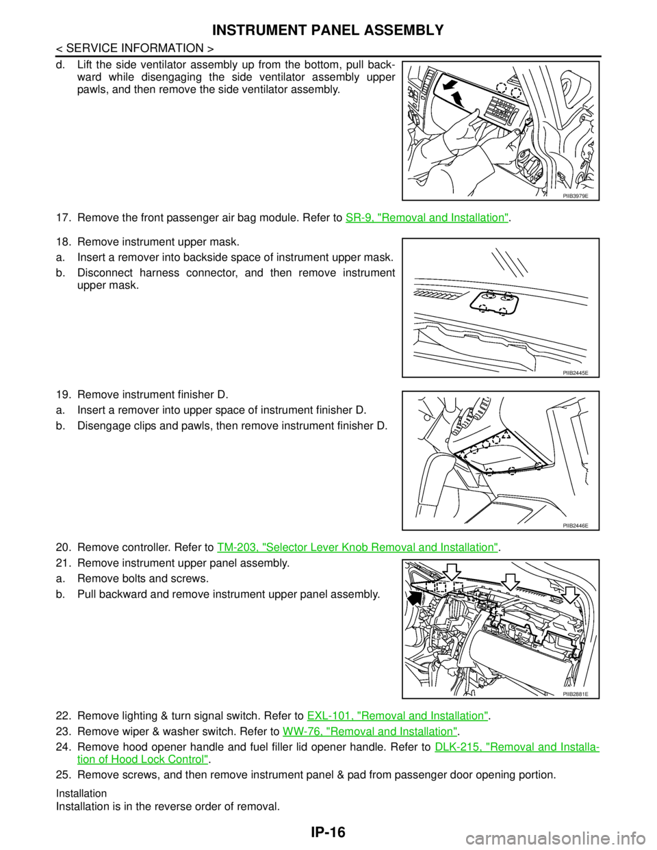
d. Lift the side ventilator assembly up from the bottom, pull back-
ward while disengaging the side ventilator assembly upper
pawls, and then remove the side ventilator assembly.
17. Remove the front passenger air bag module. Refer to SR-9, "
Removal and Installation".
18. Remove instrument upper mask.
a. Insert a remover into backside space of instrument upper mask.
b. Disconnect harness connector, and then remove instrument
upper mask.
19. Remove instrument finisher D.
a. Insert a remover into upper space of instrument finisher D.
b. Disengage clips and pawls, then remove instrument finisher D.
20. Remove controller. Refer to TM-203, "
Selector Lever Knob Removal and Installation".
21. Remove instrument upper panel assembly.
a. Remove bolts and screws.
b. Pull backward and remove instrument upper panel assembly.
22. Remove lighting & turn signal switch. Refer to EXL-101, "
Removal and Installation".
23. Remove wiper & washer switch. Refer to WW-76, "
Removal and Installation".
24. Remove hood opener handle and fuel filler lid opener handle. Refer to DLK-215, "
Removal and Installa-
tion of Hood Lock Control".
25. Remove screws, and then remove instrument panel & pad from passenger door opening portion.
Installation
Installation is in the reverse order of removal.
PIIB3979E
PIIB2445E
PIIB2446E
PIIB2881E
Page 4418 of 5883
![NISSAN TIIDA 2007 Service Repair Manual PCS-4
< FUNCTION DIAGNOSIS >[IPDM E/R]
RELAY CONTROL SYSTEM
System Description
INFOID:0000000001697580
IPDM E/R activates the internal control circuit to perform the relay ON-OFF control according to NISSAN TIIDA 2007 Service Repair Manual PCS-4
< FUNCTION DIAGNOSIS >[IPDM E/R]
RELAY CONTROL SYSTEM
System Description
INFOID:0000000001697580
IPDM E/R activates the internal control circuit to perform the relay ON-OFF control according to](/manual-img/5/57395/w960_57395-4417.png)
PCS-4
< FUNCTION DIAGNOSIS >[IPDM E/R]
RELAY CONTROL SYSTEM
System Description
INFOID:0000000001697580
IPDM E/R activates the internal control circuit to perform the relay ON-OFF control according to the input sig-
nals from various sensors and the request signals received from control units via CAN communication.
CAUTION:
IPDM E/R integrated relays cannot be removed.
Control relay Input/output Transmit unit Control partReference
page
Front fog lamp relay Front fog lamp request signal BCM (CAN) Front fog lampsEXL-19
• Headlamp high relay
Headlamp low relay High beam request signal
Low beam request signalBCM (CAN) Headlamp high
Headlamp lowEXL-8
EXL-10
Tail lamp relay Position light request signal BCM (CAN)Parking lamps
License plate lamps
Tail lamps
Illumination systemEXL-24
Front wiper relay
Front wiper high relayFront wiper request signal BCM (CAN) Front wiper motorWW-4
Rear window defogger re-
layRear window defogger re-
quest signalBCM (CAN) Rear window defoggerDEF-6
A/C relay A/C request signalBCM (CAN)
ECM (CAN)A/C compressorHAC-11
Starter relay Ignition switch START signal TCM Starter motorSTR-6
Cooling fan relay Cooling fan request signal ECM (CAN) Cooling fan relayCO-4
ECM relay ECM relay control signal ECM (CAN) ECM relayEC-124
Throttle control motor relayThrottle control motor control
signalECM (CAN)Throttle control motor re-
layEC-38
Fuel pump relay Fuel pump request signal ECM (CAN) Fuel pumpEC-38
Ignition relay Ignition switch ON signal Ignition switch Ignition relayEC-47
Page 5827 of 5883

WASHER SWITCH
WW-25
< COMPONENT DIAGNOSIS >
C
D
E
F
G
H
I
J
K
MA
B
WW
N
O
P
WASHER SWITCH
DescriptionINFOID:0000000001366617
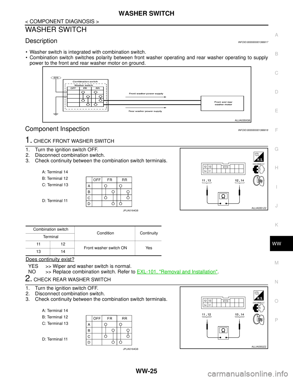
Washer switch is integrated with combination switch.
Combination switch switches polarity between front washer operating and rear washer operating to supply
power to the front and rear washer motor on ground.
Component InspectionINFOID:0000000001366618
1. CHECK FRONT WASHER SWITCH
1. Turn the ignition switch OFF.
2. Disconnect combination switch.
3. Check continuity between the combination switch terminals.
Does continuity exist?
YES >> Wiper and washer switch is normal.
NO >> Replace combination switch. Refer to EXL-101, "
Removal and Installation".
2. CHECK REAR WASHER SWITCH
1. Turn the ignition switch OFF.
2. Disconnect combination switch.
3. Check continuity between the combination switch terminals.
ALLIA0350GB
A: Terminal 14
B: Terminal 12
C: Terminal 13
D: Terminal 11
ALLIA0351ZZJPLIA0164GB
Combination switch
Condition Continuity
Te r m i n a l
11 1 2
Front washer switch ON Yes
13 14
A: Terminal 14
B: Terminal 12
C: Terminal 13
D: Terminal 11
ALLIA0352ZZJPLIA0164GB
Page 5828 of 5883
WW-26
< COMPONENT DIAGNOSIS >
WASHER SWITCH
Does continuity exist?
YES >> Wiper and washer switch is normal.
NO >> Replace combination switch. Refer to EXL-101, "
Removal and Installation".
Combination switch
Condition Continuity
Te r m i n a l
11 1 4
Rear washer switch ON Yes
12 13