Page 173 of 5883
BCS-38
< ECU DIAGNOSIS >
BCM (BODY CONTROL MODULE)
1: With Intelligent Key
2: With remote keyless entry system
3: Hatchback
Terminal LayoutINFOID:0000000001538883
TERMINAL LAYOUT
ALMIA0185ZZ
Page 174 of 5883

BCS
BCM (BODY CONTROL MODULE)
BCS-39
< ECU DIAGNOSIS >
C
D
E
F
G
H
I
J
K
L B A
O
P N
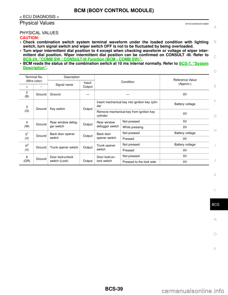
Physical ValuesINFOID:0000000001538886
PHYSICAL VALUES
CAUTION:
Check combination switch system terminal waveform under the loaded condition with lighting
switch, turn signal switch and wiper switch OFF is not to be fluctuated by being overloaded.
Turn wiper intermittent dial position to 4 except when checking waveform or voltage of wiper inter-
mittent dial position. Wiper intermittent dial position can be confirmed on CONSULT -III. Refer to
BCS-24, "
COMB SW : CONSULT-III Function (BCM - COMB SW)".
BCM reads the status of the combination switch at 10 ms internal normally. Refer to BCS-7, "
System
Description".
Terminal No.
(Wire color)Description
ConditionReference Value
(Approx.)
Signal nameInput/
Output +−
2
(B)Ground Ground — — 0V
3
(G)Ground Key switch OutputInsert mechanical key into ignition key cylin-
derBattery voltage
Remove mechanical key from ignition key
cylinder0V
4
(W)GroundRear window defog-
ger switchOutputRear window
defogger switchNot pressed 5V
While pressing 0V
5
1
(V)GroundBack door opener
switchOutputBack door
opener switchNot pressed Battery voltage
Pressed 0V
5
2
(V)Ground Trunk opener switch OutputTrunk opener
switchNot pressed Battery voltage
Pressed 0V
6
(GR)GroundDoor lock/unlock
switch (Lock) OutputDoor lock/un-
lock switchNot pressed 5V
Pressed to the lock side 0V
Page 175 of 5883
BCS-40
< ECU DIAGNOSIS >
BCM (BODY CONTROL MODULE)
7
(LG)GroundCombination switch
INPUT 5InputCombination
switchAll switch OFF
(Wiper intermittent dial 4)
1.3V
Front fog lamp switch ON
(Wiper intermittent dial 4)
1.3V
Rear fog lamp switch ON
(Wiper intermittent dial 4)
1.3V
Rear wiper switch ON
(Wiper intermittent dial 4)
1.3V
Any of the condition below
with all switch OFF
Wiper intermittent dial 1
Wiper intermittent dial 2
Wiper intermittent dial 6
Wiper intermittent dial 7
1.3V Te r m i n a l N o .
(Wire color)Description
ConditionReference Value
(Approx.)
Signal nameInput/
Output +−
JPMIA0165GB
JPMIA0167GB
JPMIA0168GB
JPMIA0169GB
JPMIA0196GB
Page 176 of 5883
BCS
BCM (BODY CONTROL MODULE)
BCS-41
< ECU DIAGNOSIS >
C
D
E
F
G
H
I
J
K
L B A
O
P N
8
(V)GroundCombination switch
INPUT 3InputCombination
switchAll switch OFF
(Wiper intermittent dial 4)
1.4V
Lighting switch HI
(Wiper intermittent dial 4)
1.3V
Lighting switch 2ND
(Wiper intermittent dial 4)
1.3V
Rear wiper switch ON
1.3V
Any of the condition below
with all switch OFF
Wiper intermittent dial 1
Wiper intermittent dial 2
Wiper intermittent dial 3
1.3V Terminal No.
(Wire color)Description
ConditionReference Value
(Approx.)
Signal nameInput/
Output +−
JPMIA0165GB
JPMIA0166GB
JPMIA0167GB
JPMIA0169GB
JPMIA0196GB
Page 177 of 5883
BCS-42
< ECU DIAGNOSIS >
BCM (BODY CONTROL MODULE)
9
(P)GroundCombination switch
INPUT 1InputCombination
switch
(Wiper intermit-
tent dial 4)All switch OFF
1.4V
Turn signal switch LH
1.3V
Turn signal switch RH
1.3V
Front wiper switch LO
1.3V
Front washer switch ON
1.3V
10
1
(Y)Ground Back door switch InputBack door
switchOFF (When back door
closed)Battery voltage
ON (When back door
opened)0V
10
2
(Y)Ground Trunk switch Input Trunk switchOFF (When trunk closed) Battery voltage
ON (When trunk opened) 0V Te r m i n a l N o .
(Wire color)Description
ConditionReference Value
(Approx.)
Signal nameInput/
Output +−
JPMIA0165GB
JPMIA0167GB
JPMIA0166GB
JPMIA0168GB
JPMIA0196GB
Page 178 of 5883

BCS
BCM (BODY CONTROL MODULE)
BCS-43
< ECU DIAGNOSIS >
C
D
E
F
G
H
I
J
K
L B A
O
P N
13
(V)GroundCombination switch
OUTPUT 1OutputCombination
switchAll switch OFF
(Wiper intermittent dial 4)0V
Front wiper switch HI
(Wiper intermittent dial 4)
Rear wiper switch INT
(Wiper intermittent dial 4)
Any of the condition below
with all switch OFF
Wiper intermittent dial 1
Wiper intermittent dial 2
Wiper intermittent dial 3
Wiper intermittent dial 6
Wiper intermittent dial 7
14
(L)GroundCombination switch
OUTPUT 3OutputCombination
switch
(Wiper intermit-
tent dial 4)All switch OFF 0V
Lighting switch AUTO
Rear fog lamp switch OFF
Front wiper switch MIST
Front wiper switch INT
Front wiper switch LO
15
(BR)GroundCombination switch
OUTPUT 5OutputCombination
switch
(Wiper intermit-
tent dial 4)All switch OFF 0V
Lighting switch 1ST
Lighting switch 2ND
Lighting switch HI
Turn signal switch RH
16
(R)Ground Stop lamp switch InputDepress the brake pedal Battery voltage
Release the brake pedal 0V
17
(Y)Ground Back up lamp signal InputShift lever in reverse Battery voltage
Other than above 0V
19
(L)—CAN-HInput/
Output——
21
(BR)GroundRoom lamp timer
controlOutputInterior room
lampOFF Battery voltage
ON 0V
22
(P)GroundBattery power sup-
plyInput — Battery voltage
23
1
(LG)Ground Rear wiper auto stop OutputIgnition switch
ONRear wiper stop position 0V
Any position other than
rear wiper stop position Terminal No.
(Wire color)Description
ConditionReference Value
(Approx.)
Signal nameInput/
Output +−
SKIA2167J
SKIA2167J
SKIA2167J
JPMIA0197GB
Page 179 of 5883
BCS-44
< ECU DIAGNOSIS >
BCM (BODY CONTROL MODULE)
24
(O)GroundIgnition power sup-
plyInputIgnition switch OFF or ACC 0V
Ignition switch ON or START Battery voltage
25
(L)GroundDoor lock/unlock
switch (Unlock) OutputDoor lock/un-
lock switchNot pressed 5V
Pressed to the unlock side 0V
26
(L)Ground Hazard switch Output Hazard switchNot pressed
Pressed 0V Te r m i n a l N o .
(Wire color)Description
ConditionReference Value
(Approx.)
Signal nameInput/
Output +−
SKIA2239J
Page 180 of 5883
BCS
BCM (BODY CONTROL MODULE)
BCS-45
< ECU DIAGNOSIS >
C
D
E
F
G
H
I
J
K
L B A
O
P N
27
(Y)GroundCombination switch
INPUT 4InputCombination
switchAll switch OFF
(Wiper intermittent dial 4)
1.4V
Lighting switch AUTO
(Wiper intermittent dial 4)
1.3V
Lighting switch 1ST
(Wiper intermittent dial 4)
1.3V
Rear wiper INT
(Wiper intermittent dial 4)
1.3V
Any of the condition below
with all switch OFF
Wiper intermittent dial 1
Wiper intermittent dial 6
1.3V Terminal No.
(Wire color)Description
ConditionReference Value
(Approx.)
Signal nameInput/
Output +−
JPMIA0165GB
JPMIA0167GB
JPMIA0166GB
JPMIA0167GB
JPMIA0196GB