Page 5628 of 5883
TM-682
< REMOVAL AND INSTALLATION >[6MT: RS6F94R]
TRANSAXLE ASSEMBLY
K9K
Tighten bolts to the specified torque.
Refer to CL-11, "
Removal and Installation" for CSC (Concentric Slave Cylinder) installation procedure.
Refer to TM-674, "
Removal and Installation" for select cable and shift cable installation procedure.
Bleed the air from the clutch hydraulic system. Refer to CL-8, "
Air Bleeding Procedure".
After installation, check for oil leakage and oil level. Refer to TM-672, "
Inspection".
“ ” mm (in)60 (2.36) 50 (1.97)
Tightening torque
N·m (kg-m, ft-lb)62.0 (6.3, 46) Bolt symbol A B
: Transaxle to engine
: Engine to transaxle
Bolt symbol A B C
Quantity 2 2 4
“ ” mm (in)50 (1.97) 80 (3.15) 65 (2.56)
Tightening torque
N·m (kg-m, ft-lb)48 (4.9, 35)
JPDIC0054ZZ
Page 5674 of 5883
![NISSAN TIIDA 2007 Service Repair Manual A/C UNIT ASSEMBLY
VTL-13
< ON-VEHICLE REPAIR >[AUTOMATIC AIR CONDITIONER]
C
D
E
F
G
H
J
K
L
MA
B
VTL
N
O
P
7. Remove console box assembly. Refer to IP-11, "Removal and Installation"
8. Remove the inst NISSAN TIIDA 2007 Service Repair Manual A/C UNIT ASSEMBLY
VTL-13
< ON-VEHICLE REPAIR >[AUTOMATIC AIR CONDITIONER]
C
D
E
F
G
H
J
K
L
MA
B
VTL
N
O
P
7. Remove console box assembly. Refer to IP-11, "Removal and Installation"
8. Remove the inst](/manual-img/5/57395/w960_57395-5673.png)
A/C UNIT ASSEMBLY
VTL-13
< ON-VEHICLE REPAIR >[AUTOMATIC AIR CONDITIONER]
C
D
E
F
G
H
J
K
L
MA
B
VTL
N
O
P
7. Remove console box assembly. Refer to IP-11, "Removal and Installation"
8. Remove the instrument stay nuts (A) and harness clamps (B),
and then remove instrument stay (1).
9. Disconnect intake sensor connector (1).
10. Remove instrument panel and pad. Refer to IP-11, "
Removal and Installation".
11. Remove side ventilator ducts. Refer to VTL-23, "
Removal and Installation".
12. Remove center ventilator ducts. Refer to VTL-23, "
Removal and Installation".
13. Remove the side kicking plates. Refer to INT-20, "
Removal and Installation".
14. Disconnect the fuel filler door cable and the rear hatch door cable (if equipped).
15. Remove A/C unit assembly bolts, steering member bolts, steering column nuts and harness clips.
16. Remove steering member, and then remove A/C unit assembly.
INSTALLATION
Installation is in the reverse order of removal.
Fill the cooling system with coolant. Refer to CO-11, "
Changing Engine Coolant" (HR16DE), CO-35, "Chang-
ing Engine Coolant" (MR18DE), CO-58, "Refilling" (K9K).
Recharge the refrigerant. Refer to HA-29, "
HFC-134a (R-134a) Service Procedure".
CAUTION:
Replace O-rings for A/C piping with new ones, and then apply compressor oil to it when installing it.
When recharging refrigerant, check for leaks.
SJIA0646E
SJIA0690E
A/C unit assembly bolt : 6.9 N·m (0.7 kg-m, 61 in-lb)
Steering member bolt : 12 N·m (1.25 kg-m, 9 ft-lb)
Steering column nut : -Refer to ST-9, "
Removal and Installation".
Page 5699 of 5883
![NISSAN TIIDA 2007 Service Repair Manual VTL-38
< ON-VEHICLE REPAIR >[MANUAL AIR CONDITIONER]
A/C UNIT ASSEMBLY
7. Remove console box assembly. Refer to IP-11, "Removal and Installation" .
8. Remove instrument stay nuts (A) and harness clamp NISSAN TIIDA 2007 Service Repair Manual VTL-38
< ON-VEHICLE REPAIR >[MANUAL AIR CONDITIONER]
A/C UNIT ASSEMBLY
7. Remove console box assembly. Refer to IP-11, "Removal and Installation" .
8. Remove instrument stay nuts (A) and harness clamp](/manual-img/5/57395/w960_57395-5698.png)
VTL-38
< ON-VEHICLE REPAIR >[MANUAL AIR CONDITIONER]
A/C UNIT ASSEMBLY
7. Remove console box assembly. Refer to IP-11, "Removal and Installation" .
8. Remove instrument stay nuts (A) and harness clamps (B), and
then remove instrument stay (1).
9. Disconnect thermo control amp. connector (1).
10. Remove instrument panel and pad. Refer to IP-11, "
Removal and Installation".
11. Remove side ventilator ducts. Refer to VTL-48, "
Removal and Installation".
12. Remove center ventilator ducts. Refer to VTL-48, "
Removal and Installation".
13. Remove side kicking plates. Refer to INT-20, "
Removal and Installation".
14. Disconnect the fuel filler door cable and the rear hatch door cable.
15. Remove A/C unit assembly bolts, steering member bolts, steering column nuts and harness clips.
16. Remove steering member, and then remove A/C unit assembly.
INSTALLATION
Installation is in the reverse order of removal.
Fill the cooling system. Refer to CO-11, "
Changing Engine Coolant" (HR16DE), CO-35, "Changing Engine
Coolant" (MR18DE), CO-58, "Refilling" (K9K).
Recharge the refrigerant.
CAUTION:
Replace O-rings for A/C piping with new ones, and apply compressor oil when installing.
When recharging refrigerant, check for leaks.
SJIA0646E
SJIA0647E
A/C unit assembly bolt : 6.9 N·m (0.7 kg-m, 61 in-lb)
Steering member bolt : 12 N·m (1.25 kg-m, 9 ft-lb)
Steering column nut : Refer to ST-9, "
Removal and Installation".
Page 5745 of 5883

WCS-30
< COMPONENT DIAGNOSIS >
PARKING BRAKE SWITCH SIGNAL CIRCUIT
PARKING BRAKE SWITCH SIGNAL CIRCUIT
DescriptionINFOID:0000000001722969
Transmits the parking brake switch signal to the combination meter.
Component Function CheckINFOID:0000000001724686
1.COMBINATION METER INPUT SIGNAL
1. Start engine.
2. Monitor “BRAKE” warning lamp while applying and releasing the parking brake.
>> Inspection End.
Diagnosis ProcedureINFOID:0000000001724687
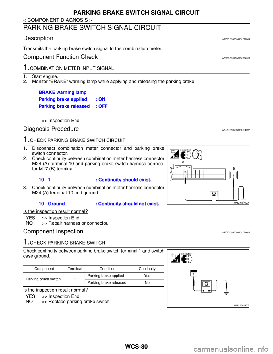
1.CHECK PARKING BRAKE SWITCH CIRCUIT
1. Disconnect combination meter connector and parking brake
switch connector.
2. Check continuity between combination meter harness connector
M24 (A) terminal 10 and parking brake switch harness connec-
tor M17 (B) terminal 1.
3. Check continuity between combination meter harness connector
M24 (A) terminal 10 and ground.
Is the inspection result normal?
YES >> Inspection End.
NO >> Repair harness or connector.
Component InspectionINFOID:0000000001724688
1.CHECK PARKING BRAKE SWITCH
Check continuity between parking brake switch terminal 1 and switch
case ground.
Is the inspection result normal?
YES >> Inspection End.
NO >> Replace parking brake switch.BRAKE warning lamp
Parking brake applied : ON
Parking brake released : OFF
10 - 1 : Continuity should exist.
10 - Ground : Continuity should not exist.
AWNIA0273ZZ
Component Terminal Condition Continuity
Parking brake switch 1Parking brake applied Yes
Parking brake released No
AWNIA0018ZZ
Page 5794 of 5883

WCS
THE PARKING BRAKE RELEASE WARNING CONTINUES SOUNDING, OR
DOES NOT SOUND
WCS-79
< SYMPTOM DIAGNOSIS >
C
D
E
F
G
H
I
J
K
L
MB A
O
P
THE PARKING BRAKE RELEASE WARNING CONTINUES SOUNDING, OR
DOES NOT SOUND
DescriptionINFOID:0000000001722967
The parking brake warning buzzer sounds continuously during vehicle travel though the parking brake is
released
The parking brake warning buzzer does not sound at all even though driving the vehicle with the parking
brake applied.
Diagnosis ProcedureINFOID:0000000001722968
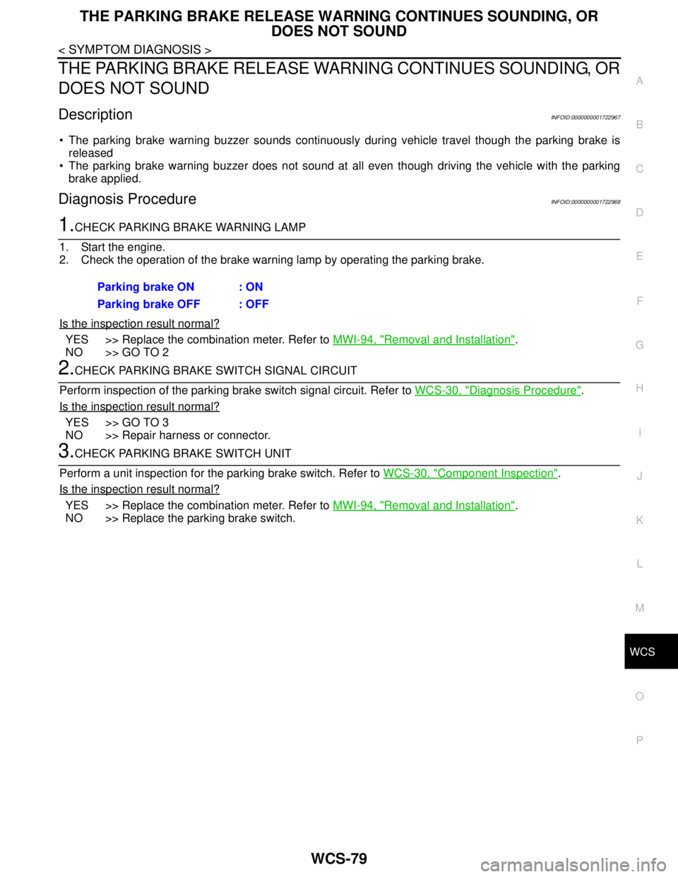
1.CHECK PARKING BRAKE WARNING LAMP
1. Start the engine.
2. Check the operation of the brake warning lamp by operating the parking brake.
Is the inspection result normal?
YES >> Replace the combination meter. Refer to MWI-94, "Removal and Installation".
NO >> GO TO 2
2.CHECK PARKING BRAKE SWITCH SIGNAL CIRCUIT
Perform inspection of the parking brake switch signal circuit. Refer to WCS-30, "
Diagnosis Procedure".
Is the inspection result normal?
YES >> GO TO 3
NO >> Repair harness or connector.
3.CHECK PARKING BRAKE SWITCH UNIT
Perform a unit inspection for the parking brake switch. Refer to WCS-30, "
Component Inspection".
Is the inspection result normal?
YES >> Replace the combination meter. Refer to MWI-94, "Removal and Installation".
NO >> Replace the parking brake switch.Parking brake ON : ON
Parking brake OFF : OFF