2007 NISSAN QASHQAI Engine compartment
[x] Cancel search: Engine compartmentPage 6 of 297
Downloaded from www.Manualslib.com manuals search engine 0Illustrated table of contents
Illustrated table of contents
Air bag system ......................................................... 0-2
Exterior front and rear .............................................. 0-3
Instrument and control layout ................................... 0-4
Left (LHD) and Right-hand drive (RHD)
models ............................................................... 0-5
Meters and gauges .................................................. 0-6
Engine compartment ................................................ 0-7 HR16DE engine (Type A) ................................... 0-8
HR16DE engine (Type B) ................................... 0-8
MR20DE engine ................................................. 0-9
Euro 4 K9K engine ............................................. 0-11
Euro 5 K9K engine ............................................. 0-11
M9R engine ........................................................ 0-12
R9M engine ........................................................ 0-13
Page 12 of 297
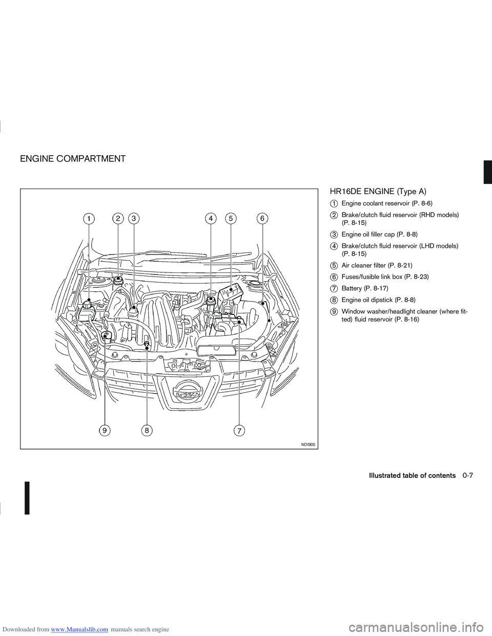
Downloaded from www.Manualslib.com manuals search engine HR16DE ENGINE (Type A)
j
1Engine coolant reservoir (P. 8-6)
j2Brake/clutch fluid reservoir (RHD models)
(P. 8-15)
j3Engine oil filler cap (P. 8-8)
j4Brake/clutch fluid reservoir (LHD models)
(P. 8-15)
j5Air cleaner filter (P. 8-21)
j6Fuses/fusible link box (P. 8-23)
j7Battery (P. 8-17)
j8Engine oil dipstick (P. 8-8)
j9Window washer/headlight cleaner (where fit-
ted) fluid reservoir (P. 8-16)
NDI905
ENGINE COMPARTMENT
Illustrated table of contents0-7
Page 22 of 297
Downloaded from www.Manualslib.com manuals search engine REAR SEAT(S)
Folding (5-seater)
The luggage compartment loading capacity can be
increased by folding the rear seats forward.
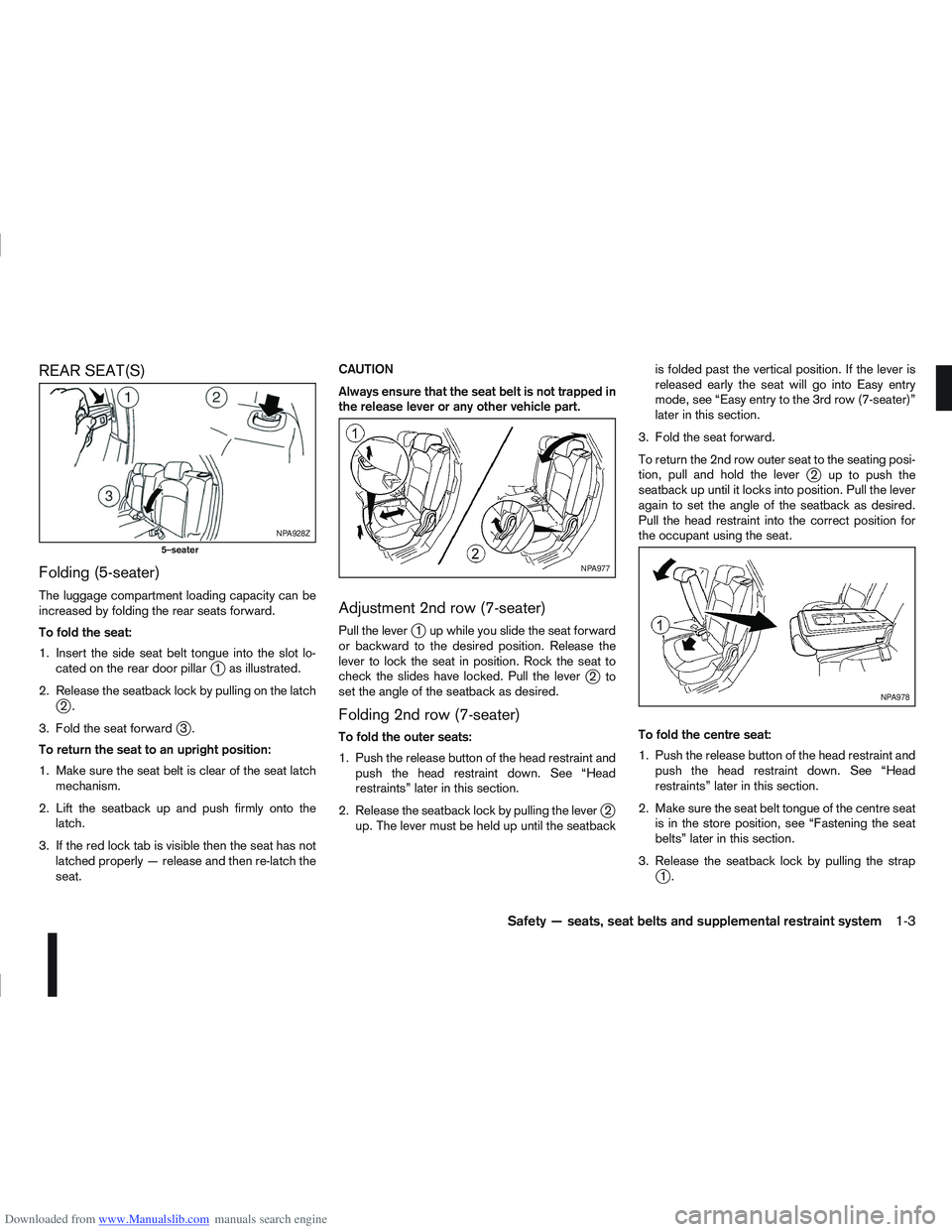
To fold the seat:
1. Insert the side seat belt tongue into the slot lo-cated on the rear door pillar
j1 as illustrated.
2. Release the seatback lock by pulling on the latch
j2.
3. Fold the seat forward
j3.
To return the seat to an upright position:
1. Make sure the seat belt is clear of the seat latch mechanism.
2. Lift the seatback up and push firmly onto the latch.
3. If the red lock tab is visible then the seat has not latched properly — release and then re-latch the
seat. CAUTION
Always ensure that the seat belt is not trapped in
the release lever or any other vehicle part.
Adjustment 2nd row (7-seater)
Pull the leverj1 up while you slide the seat forward
or backward to the desired position. Release the
lever to lock the seat in position. Rock the seat to
check the slides have locked. Pull the lever
j2to
set the angle of the seatback as desired.
Folding 2nd row (7-seater)
To fold the outer seats:
1. Push the release button of the head restraint and push the head restraint down. See “Head
restraints” later in this section.
2. Release the seatback lock by pulling the lever
j2
up. The lever must be held up until the seatback is folded past the vertical position. If the lever is
released early the seat will go into Easy entry
mode, see “Easy entry to the 3rd row (7-seater)”
later in this section.
3. Fold the seat forward.
To return the 2nd row outer seat to the seating posi-
tion, pull and hold the lever
j2 uptopushthe
seatback up until it locks into position. Pull the lever
again to set the angle of the seatback as desired.
Pull the head restraint into the correct position for
the occupant using the seat.
To fold the centre seat:
1. Push the release button of the head restraint and push the head restraint down. See “Head
restraints” later in this section.
2. Make sure the seat belt tongue of the centre seat is in the store position, see “Fastening the seat
belts” later in this section.
3. Release the seatback lock by pulling the strap
j1.
NPA928Z
5–seater
NPA977
NPA978
Safety — seats, seat belts and supplemental restraint system1-3
Page 43 of 297
Downloaded from www.Manualslib.com manuals search engine Rear facing
If you must install a child restraint system in the front
seat, follow these steps:
1. Deactivate the front passenger air bag. See“Front passenger air bag deactivation system”
earlier in this section for further details.
2. Move the seat to the rearmost position.
3. Adjust the head restraint to its highest position. Remove it if it interferes with the child restraint
installation. In such situations, securely store the
head restraint in the luggage compartment so
that it does not become a dangerous projectile
during a sudden stop or in an accident.
4. Position the child restraint system in the front passenger seat.
Always follow the child restraint system manu-
facturer’s instructions for installation and use. 5. Route the seat belt tongue through the child re-
straint system and insert it into the buckle until
you hear and feel the latch engage.
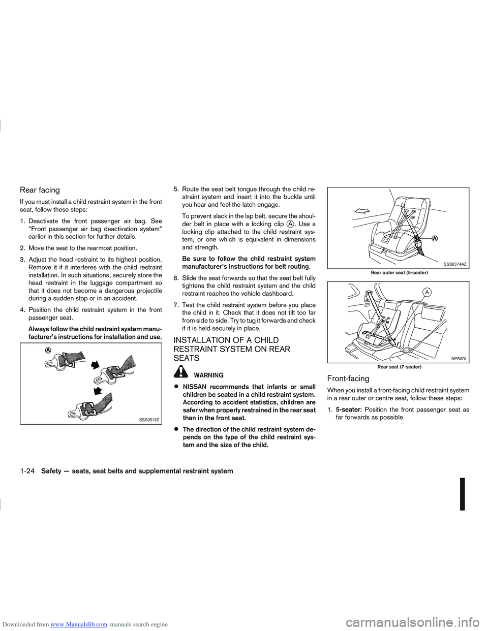
To prevent slack in the lap belt, secure the shoul-
der belt in place with a locking clip
jA. Use a
locking clip attached to the child restraint sys-
tem, or one which is equivalent in dimensions
and strength.
Be sure to follow the child restraint system
manufacturer’s instructions for belt routing.
6. Slide the seat forwards so that the seat belt fully tightens the child restraint system and the child
restraint reaches the vehicle dashboard.
7. Test the child restraint system before you place the child in it. Check that it does not tilt too far
from side to side. Try to tug it forwards and check
if it is held securely in place.
INSTALLATION OF A CHILD
RESTRAINT SYSTEM ON REAR
SEATS
WARNING
NISSAN recommends that infants or small
children be seated in a child restraint system.
According to accident statistics, children are
safer when properly restrained in the rear seat
than in the front seat.
The direction of the child restraint system de-
pends on the type of the child restraint sys-
tem and the size of the child.
Front-facing
When you install a front-facing child restraint system
in a rear outer or centre seat, follow these steps:
1.5-seater: Position the front passenger seat as
far forwards as possible.
SSS0513Z
SSS0374AZ
Rear outer seat (5-seater)
NPA975
Rear seat (7-seater)
1-24Safety — seats, seat belts and supplemental restraint system
Page 46 of 297
Downloaded from www.Manualslib.com manuals search engine ISOFIX child seat – where fitted) to the vehicle
ISOFIX brackets located in slots on the slope of
the rear outer seat cushions (refer to the ISOFIX
label for appropriate locations).
4. After attaching the child restraint and before plac- ing the child in it, use force to check that it does
not tilt too far from side to side and tug it forward
to make sure that the child restraint is securely
held in place. Make sure that both ISOFIX an-
chorages have latched correctly.
5. Make sure that the child restraint is properly se- cured prior to each use.
NOTE
For forward facing ISOFIX child restraint posi-
tion on the rear seat, slide the front seat as far
forwards as possible.
For rearward facing ISOFIX child restraint po-
sition on the rear seat, slide the front seat
backwards until it touches the edge of the
child restraint.
TOP TETHER STRAP FOR CHILD
RESTRAINT
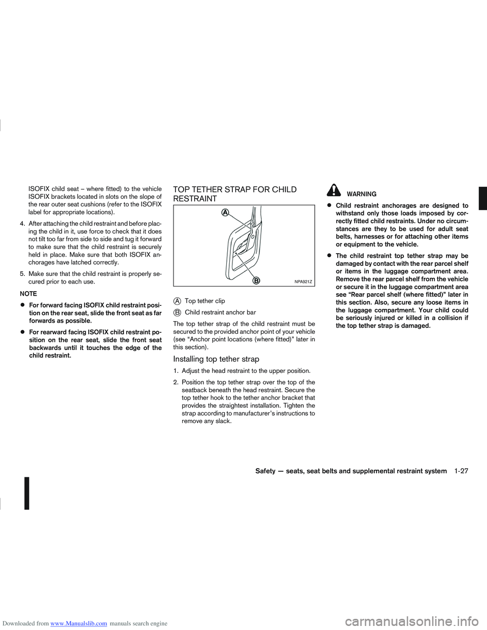
j
A Top tether clip
jB Child restraint anchor bar
The top tether strap of the child restraint must be
secured to the provided anchor point of your vehicle
(see “Anchor point locations (where fitted)” later in
this section).
Installing top tether strap
1. Adjust the head restraint to the upper position.
2. Position the top tether strap over the top of the seatback beneath the head restraint. Secure the
top tether hook to the tether anchor bracket that
provides the straightest installation. Tighten the
strap according to manufacturer’s instructions to
remove any slack.
WARNING
Child restraint anchorages are designed to
withstand only those loads imposed by cor-
rectly fitted child restraints. Under no circum-
stances are they to be used for adult seat
belts, harnesses or for attaching other items
or equipment to the vehicle.
The child restraint top tether strap may be
damaged by contact with the rear parcel shelf
or items in the luggage compartment area.
Remove the rear parcel shelf from the vehicle
or secure it in the luggage compartment area
see “Rear parcel shelf (where fitted)” later in
this section. Also, secure any loose items in
the luggage compartment. Your child could
be seriously injured or killed in a collision if
the top tether strap is damaged.
NPA921Z
Safety — seats, seat belts and supplemental restraint system1-27
Page 47 of 297
Downloaded from www.Manualslib.com manuals search engine Anchor point locations (where fitted)
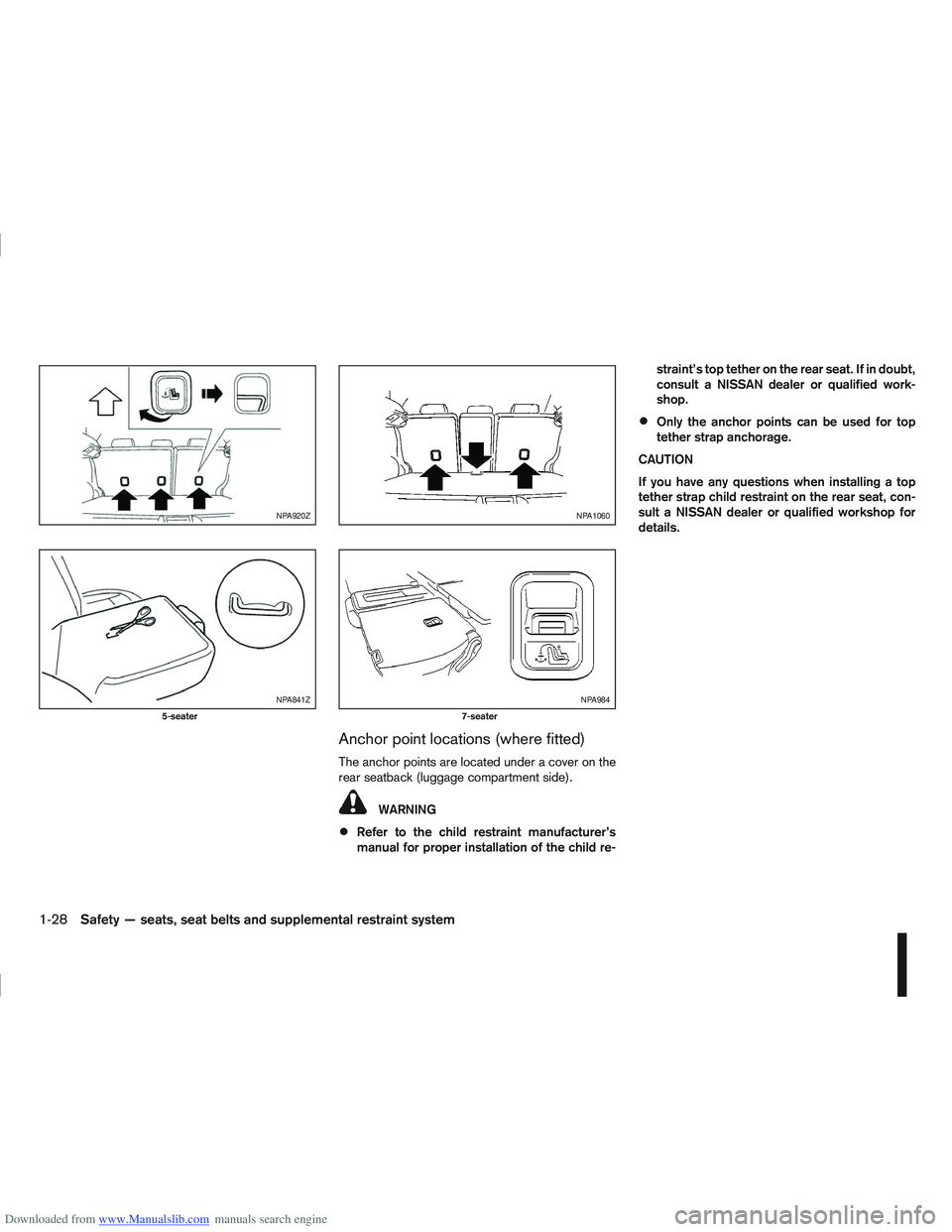
The anchor points are located under a cover on the
rear seatback (luggage compartment side).
WARNING
Refer to the child restraint manufacturer’s
manual for proper installation of the child re-straint’s top tether on the rear seat. If in doubt,
consult a NISSAN dealer or qualified work-
shop.
Only the anchor points can be used for top
tether strap anchorage.
CAUTION
If you have any questions when installing a top
tether strap child restraint on the rear seat, con-
sult a NISSAN dealer or qualified workshop for
details.
NPA920Z
NPA841Z
5-seater
NPA1060
NPA984
7-seater
1-28Safety — seats, seat belts and supplemental restraint system
Page 49 of 297
Downloaded from www.Manualslib.com manuals search engine 2Instruments and controls
Instruments and controls
Meters and gauges .................................................. 2-2
Speedometer...................................................... 2-2
Fuel gauge ......................................................... 2-2
Tachometer ........................................................ 2-2
Engine coolant temperature gauge ...................... 2-2
Warning/indicator lights and audible reminders ........ 2-3 Checking bulbs .................................................. 2-3
Warning lights .................................................... 2-3
Indicator lights .................................................... 2-7
Audible reminders............................................... 2-9
Vehicle information display ....................................... 2-11 Warnings and alerts............................................ 2-12
Odometer/twin trip odometer .............................. 2-16
Brightness control .............................................. 2-16
Trip computer ..................................................... 2-16
Settings menu .................................................... 2-18
Cruise control/Speed limiter indicator (where
fitted).................................................................. 2-21
Wiper and washer switch ........................................ 2-21 Windscreen ........................................................ 2-22
Rear window ...................................................... 2-23
Defogger switch ...................................................... 2-23 Rear window defogger ....................................... 2-23
Outside mirror defogger (where fitted) ................ 2-24
Headlight and turn signal switch............................... 2-24 Xenon headlights (where fitted) ........................... 2-24
Headlight switch ................................................. 2-24
Turn signal switch ............................................... 2-26
Fog light switch ....................................................... 2-26 Front fog light (where fitted) ................................ 2-26 Rear fog light ...................................................... 2-27
Headlight aiming control .......................................... 2-27 Headlight aiming control switch (where fitted) ..... 2-27
Automatic aiming control (xenon headlights) ........ 2-27
Headlight cleaner (where fitted) ............................... 2-28
Hazard warning flasher switch ................................. 2-28
Horn ........................................................................\
2-29
Seat heating (where fitted) ....................................... 2-29
Power outlet ............................................................ 2-30
Storage ................................................................... 2-31 Storage trays ...................................................... 2-31
Glove box ........................................................... 2-31
Console box ....................................................... 2-32
Cup holders ....................................................... 2-32
Bottle holder ....................................................... 2-32
Map pocket (where fitted) ................................... 2-32
Seat pocket (where fitted)................................... 2-32
Roof rail (where fitted) ........................................ 2-32
Rear parcel shelf (where fitted) ................................ 2-33
Tonneau cover (where fitted).................................... 2-33
Windows ................................................................. 2-34 Power windows .................................................. 2-34
C-View® glass roof (where fitted) ............................ 2-36 Sunshade operation ............................................ 2-36
System reinitialisation.......................................... 2-37
Interior lights ............................................................ 2-37 Front Room light ................................................. 2-37
Map lights (where fitted) ..................................... 2-38
Rear room/reading light ...................................... 2-38
Luggage compartment light ................................ 2-38
Page 62 of 297
Downloaded from www.Manualslib.com manuals search engine For more information, see “Seat belts” in the
“1. Safety — seats, seat belts and supplemental
restraint system” section
j4 Ignition knob warning (Intelligent Key
models)
The warning appears when the ignition knob is left
in the Acc or “OFF” position instead of completely
being turned to the LOCK position.
If this warning appears, turn the ignition knob to the
LOCK position.
When the ignition knob is in the ON position, a
buzzer will sound twice and the ignition knob warn-
ing shows when the ignition knob is turned to the
Acc or “OFF” position. This is to warn the driver that
the ignition knob is not in the LOCK position.
MT models:
Depress the ignition PUSH release button and turn
the ignition knob to the LOCK position.
AT or CVT models:
Make sure the gear selector lever is in the P (Park)
position and then turn the ignition switch to the
LOCK position.
See “Ignition knob (where fitted)” in the “5. Starting
and driving” section for further details.
CAUTION
The steering wheel can only be locked when
the ignition knob is in the LOCK position. Make
sure the ignition knob is in the LOCK position
before leaving the vehicle.
The emergency key can only be removed at
the LOCK position. Make sure the ignition
knob is in the LOCK position before removing
the emergency key.
See “Steering lock” in the “5. Starting and driving”
section for further details.
j5 Steering wheel lock warning
The warning appears when the ignition knob is
pressed, but not turned to the Acc or “OFF” posi-
tion within a short period. Move the steering wheel
to release the lock and turn the ignition knob to Acc
or ON. The warning will turn off in approximately 5
seconds.
See “Steering lock” in the “5. Starting and driving”
section for further details.
j6 Brake/Clutch warning (where fitted)
When starting your vehicle, it is necessary to oper-
ate the brake (CVT and AT models) or clutch pedal
(MT models).
For more information, see “Starting the engine” in
the “5. Starting and driving” section.
j7 Handbrake reminder
The reminder will come on if the handbrake is on
whilst the vehicle is being driven.
A buzzer will also sound.
j8 Intelligent Key detection warning
If the Intelligent Key is taken outside of the vehicle
ID recognition zone while the ignition knob is in the
Acc or ON position, the Intelligent Key detection
warning will be displayed and a buzzer will sound.
The Intelligent Key detection warning disappears
when the Intelligent Key is placed back in the pas-
senger compartment.
The message also appears when you try to start the
vehicle if the Intelligent Key is not detected within
the vehicle.
For more information, see “Integrated keyfob/re-
mote control system” in the “3. Pre-driving checks
and adjustments” section.
j9 Intelligent Key low battery warning
The Intelligent Key low battery warning may show if
a low battery voltage is detected when the ignition
knob is turned from “OFF” to the ON position.
For more information, see “Integrated keyfob/Intel-
ligent Key battery replacement” in the “8. Mainte-
nance and do-it-yourself” section.
j10Intelligent Key system fault warning
CAUTION
If the Intelligent Key system fault warning comes
on, it may indicate a system malfunction. We rec-
ommend that you contact a NISSAN dealer or
qualified workshop for repair.
Instruments and controls2-13