Page 852 of 2896
![NISSAN LATIO 2007 Service Repair Manual WHEEL SENSORS
BRC-33
[ABS]
C
D
E
G
H
I
J
K
L
MA
B
BRC
Revision: June 20062007 Versa
WHEEL SENSORSPFP:47910
Removal and InstallationEFS006L4
NOTE:
The top portion of the figure (front side) shows view NISSAN LATIO 2007 Service Repair Manual WHEEL SENSORS
BRC-33
[ABS]
C
D
E
G
H
I
J
K
L
MA
B
BRC
Revision: June 20062007 Versa
WHEEL SENSORSPFP:47910
Removal and InstallationEFS006L4
NOTE:
The top portion of the figure (front side) shows view](/manual-img/5/57361/w960_57361-851.png)
WHEEL SENSORS
BRC-33
[ABS]
C
D
E
G
H
I
J
K
L
MA
B
BRC
Revision: June 20062007 Versa
WHEEL SENSORSPFP:47910
Removal and InstallationEFS006L4
NOTE:
The top portion of the figure (front side) shows view from LH side of vehicle. RH side is the mirror image.
REMOVAL
Pay attention to the following when removing wheel sensor.
CAUTION:
�As much as possible, avoid rotating wheel sensor when removing it. Pull wheel sensors out with-
out pulling on sensor harness.
�Take care to avoid damaging wheel sensor edges or rotor teeth. Remove wheel sensor first before
removing front or rear wheel hub. This is to avoid damage to wheel sensor wiring and loss of sen-
sor function.
INSTALLATION
Pay attention to the following when installing wheel sensor. Tighten installation bolts and nuts to the specified
torques.
�When installing, make sure there is no foreign material such as iron chips on and in the mounting hole of
the wheel sensor. Make sure no foreign material has been caught in the sensor rotor. Remove any foreign
material and clean the mount.
�When installing front wheel sensor, press rubber grommets of strut bracket and body all the way in until
they get locked, and be careful not to apply a twist to harness. Harness should not be twisted after instal-
lation. (Install it with harness paint mark on body side grommet facing front of vehicle, and the strut side
grommet facing outside of vehicle.)
A. Front B. Rear 1. Front wheel sensor connector (LH)
2. Front wheel sensor (LH) 3. Rear wheel sensor (LH) 4. Rear wheel sensor connector (LH)
5. Rear wheel sensor connector (RH) 6. Rear wheel sensor (RH) 7. Side member
8. Left 9. Right : Front
Refer to GI section for symbol marks in the figure.
SFIA3090E
Page 853 of 2896
BRC-34
[ABS]
WHEEL SENSORS
Revision: June 20062007 Versa
�When installing rear wheel sensor, press rubber grommets of suspension arm bracket and harness of side
member all the way in until they get locked, and be careful not to apply a twist to harness. Harness should
not be twisted after installation. (Aim the paint mark upward of vehicle.)
Page 854 of 2896
SENSOR ROTOR
BRC-35
[ABS]
C
D
E
G
H
I
J
K
L
MA
B
BRC
Revision: June 20062007 Versa
SENSOR ROTORPFP:47970
Removal and InstallationEFS006L5
Sensor rotor cannot be disassembled. To replace sensor rotor, replace hub bearing assembly. Refer to FA X -5 ,
"FRONT WHEEL HUB AND KNUCKLE" in “FAX” section, refer to RAX-4, "WHEEL HUB" in “RAX” section.
Page 858 of 2896

CL-1
CLUTCH
C TRANSMISSION/TRANSAXLE
CONTENTS
D
E
F
G
H
I
J
K
L
M
SECTION CL
A
B
CL
Revision: June 20062007 Versa PRECAUTIONS .......................................................... 2
Precautions for Supplemental Restraint System
(SRS) “AIR BAG” and “SEAT BELT PRE-TEN-
SIONER” .................................................................. 2
Service Notice or Precautions .................................. 2
PREPARATION ........................................................... 3
Special Service Tools ............................................... 3
Commercial Service Tools ........................................ 3
NOISE, VIBRATION AND HARSHNESS (NVH)
TROUBLESHOOTING ................................................ 4
NVH Troubleshooting Chart ..................................... 4
CLUTCH PEDAL ........................................................ 5
On-vehicle Inspection and Adjustment ..................... 5
Removal and Installation .......................................... 7
COMPONENTS .................................................... 7
REMOVAL ............................................................. 7
INSPECTION AFTER REMOVAL ......................... 7
INSTALLATION ..................................................... 7
CLUTCH FLUID .......................................................... 8
Air Bleeding Procedure ............................................ 8
CLUTCH MASTER CYLINDER .................................. 9
Removal and Installation .......................................... 9
REMOVAL ............................................................. 9
INSTALLATION ..................................................... 9CSC (CONCENTRIC SLAVE CYLINDER) ................ 11
Removal and Installation ........................................ 11
REMOVAL ........................................................... 11
INSTALLATION ................................................... 11
CLUTCH PIPING ....................................................... 12
Removal and Installation ........................................ 12
REMOVAL ........................................................... 12
INSTALLATION ................................................... 12
CLUTCH DISC, CLUTCH COVER AND FLYWHEEL ... 13
Removal and Installation ........................................ 13
COMPONENTS ................................................... 13
REMOVAL ........................................................... 13
INSPECTION AND ADJUSTMENT AFTER
REMOVAL ........................................................... 13
INSTALLATION ................................................... 14
SERVICE DATA AND SPECIFICATIONS (SDS) ...... 16
Clutch Control System ............................................ 16
Clutch Pedal ........................................................... 16
Clutch Disc ............................................................. 16
Clutch Cover ........................................................... 16
Page 861 of 2896

CL-4
NOISE, VIBRATION AND HARSHNESS (NVH) TROUBLESHOOTING
Revision: June 20062007 Versa
NOISE, VIBRATION AND HARSHNESS (NVH) TROUBLESHOOTINGPFP:00003
NVH Troubleshooting ChartECS00FSV
Use the chart below to help you find the cause of the symptom. The numbers indicate the order of the inspec-
tion. If necessary, repair or replace these parts.
Reference pageCL-5CL-8EM-73CL-11CL-13EM-103
SUSPECTED PARTS (Possible cause)
CLUTCH PEDAL (Inspection and adjustment)
CLUTCH LINE (Air in line)
ENGINE MOUNTING (Loose)
CSC (Concentric slave cylinder) (Worn, dirty or damaged)
CLUTCH DISC (Out of true)
CLUTCH DISC (Runout is excessive)
CLUTCH DISC (Lining broken)
CLUTCH DISC (Dirty or burned)
CLUTCH DISC (Oily)
CLUTCH DISC (Worn out)
CLUTCH DISC (Hardened)
CLUTCH DISC (Lack of spline grease)
DIAPHRAGM SPRING (Damaged)
DIAPHRAGM SPRING (Out of tip alignment)
PRESSURE PLATE (Distortion)
FLYWHEEL (Distortion)
SymptomClutch grabs/chatters 1 2 2 2 2 2
Clutch pedal spongy 1
Clutch noisy 1
Clutch slips 1 2 2 3 4 5
Clutch does not disengage 1 2 5 5 5 5 5 5 6 6 7
Page 870 of 2896

CLUTCH DISC, CLUTCH COVER AND FLYWHEEL
CL-13
D
E
F
G
H
I
J
K
L
MA
B
CL
Revision: June 20062007 Versa
CLUTCH DISC, CLUTCH COVER AND FLYWHEELPFP:30100
Removal and InstallationECS00FT2
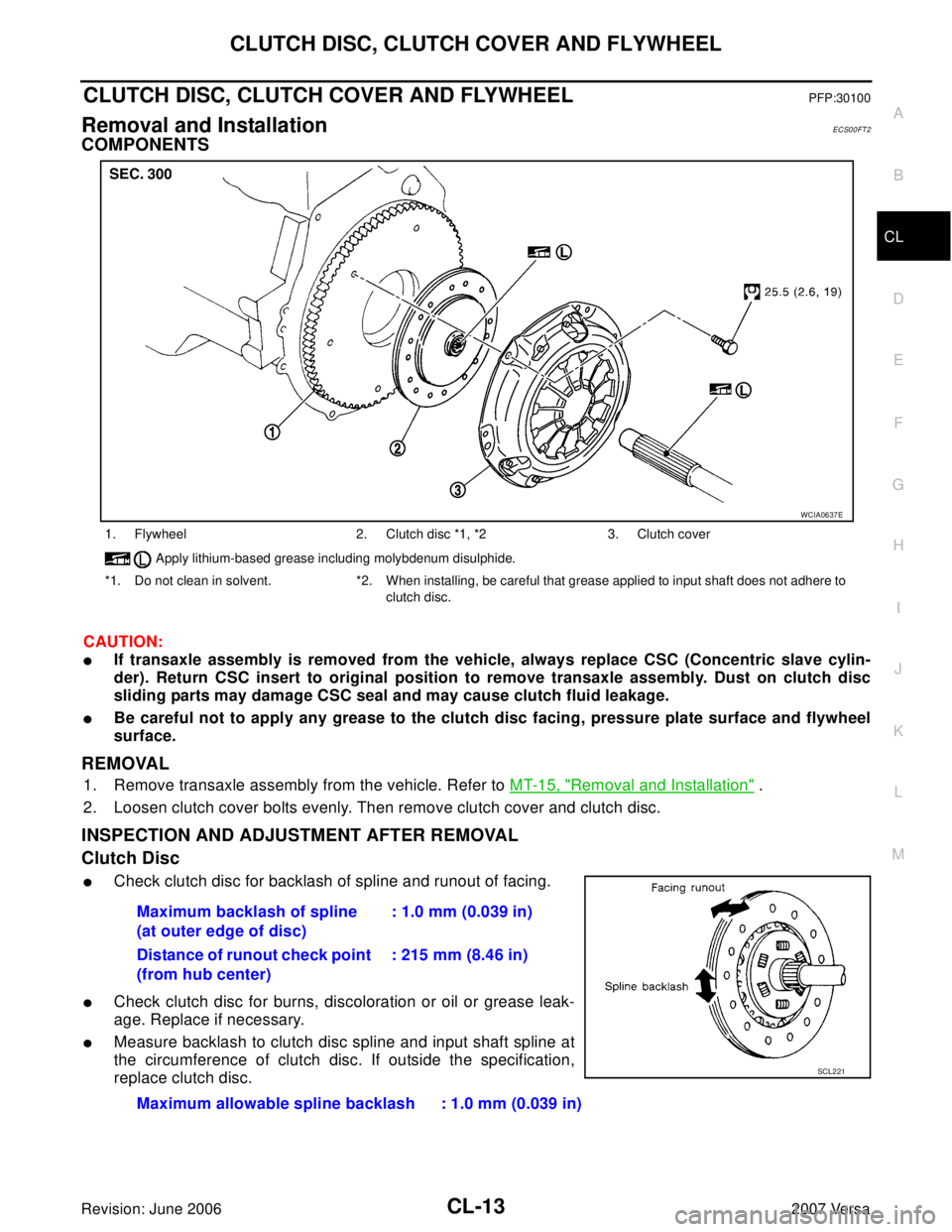
COMPONENTS
CAUTION:
�If transaxle assembly is removed from the vehicle, always replace CSC (Concentric slave cylin-
der). Return CSC insert to original position to remove transaxle assembly. Dust on clutch disc
sliding parts may damage CSC seal and may cause clutch fluid leakage.
�Be careful not to apply any grease to the clutch disc facing, pressure plate surface and flywheel
surface.
REMOVAL
1. Remove transaxle assembly from the vehicle. Refer to MT-15, "Removal and Installation" .
2. Loosen clutch cover bolts evenly. Then remove clutch cover and clutch disc.
INSPECTION AND ADJUSTMENT AFTER REMOVAL
Clutch Disc
�Check clutch disc for backlash of spline and runout of facing.
�Check clutch disc for burns, discoloration or oil or grease leak-
age. Replace if necessary.
�Measure backlash to clutch disc spline and input shaft spline at
the circumference of clutch disc. If outside the specification,
replace clutch disc.
1. Flywheel 2. Clutch disc *1, *2 3. Clutch cover
Apply lithium-based grease including molybdenum disulphide.
*1. Do not clean in solvent. *2. When installing, be careful that grease applied to input shaft does not adhere to
clutch disc.
WCIA0637E
Maximum backlash of spline
(at outer edge of disc): 1.0 mm (0.039 in)
Distance of runout check point
(from hub center): 215 mm (8.46 in)
Maximum allowable spline backlash : 1.0 mm (0.039 in)
SCL221
Page 871 of 2896

CL-14
CLUTCH DISC, CLUTCH COVER AND FLYWHEEL
Revision: June 20062007 Versa
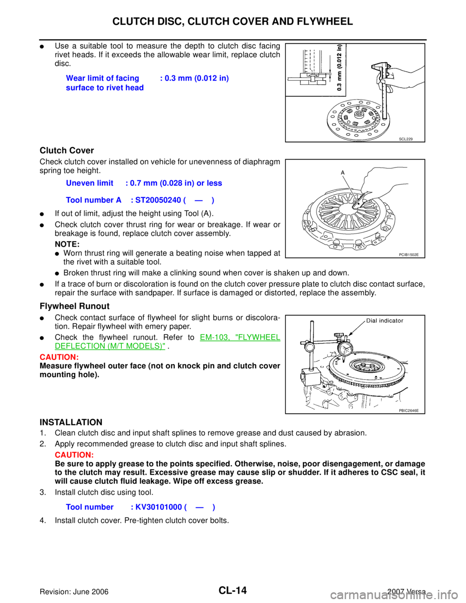
�Use a suitable tool to measure the depth to clutch disc facing
rivet heads. If it exceeds the allowable wear limit, replace clutch
disc.
Clutch Cover
Check clutch cover installed on vehicle for unevenness of diaphragm
spring toe height.
�If out of limit, adjust the height using Tool (A).
�Check clutch cover thrust ring for wear or breakage. If wear or
breakage is found, replace clutch cover assembly.
NOTE:
�Worn thrust ring will generate a beating noise when tapped at
the rivet with a suitable tool.
�Broken thrust ring will make a clinking sound when cover is shaken up and down.
�If a trace of burn or discoloration is found on the clutch cover pressure plate to clutch disc contact surface,
repair the surface with sandpaper. If surface is damaged or distorted, replace the assembly.
Flywheel Runout
�Check contact surface of flywheel for slight burns or discolora-
tion. Repair flywheel with emery paper.
�Check the flywheel runout. Refer to EM-103, "FLYWHEEL
DEFLECTION (M/T MODELS)" .
CAUTION:
Measure flywheel outer face (not on knock pin and clutch cover
mounting hole).
INSTALLATION
1. Clean clutch disc and input shaft splines to remove grease and dust caused by abrasion.
2. Apply recommended grease to clutch disc and input shaft splines.
CAUTION:
Be sure to apply grease to the points specified. Otherwise, noise, poor disengagement, or damage
to the clutch may result. Excessive grease may cause slip or shudder. If it adheres to CSC seal, it
will cause clutch fluid leakage. Wipe off excess grease.
3. Install clutch disc using tool.
4. Install clutch cover. Pre-tighten clutch cover bolts.Wear limit of facing
surface to rivet head: 0.3 mm (0.012 in)
SCL229
Uneven limit : 0.7 mm (0.028 in) or less
Tool number A : ST20050240 ( — )
PCIB1502E
PBIC2646E
Tool number : KV30101000 ( — )
Page 872 of 2896
CLUTCH DISC, CLUTCH COVER AND FLYWHEEL
CL-15
D
E
F
G
H
I
J
K
L
MA
B
CL
Revision: June 20062007 Versa
5. Tighten clutch cover bolts evenly in two steps in the order
shown. Refer to CL-13, "
COMPONENTS" .
6. Install transaxle assembly. Refer to MT-15, "
Removal and Instal-
lation" .
PCIB1772E