Page 1531 of 2896

EC-362Revision: June 2006
DTC P0444, P0445 EVAP CANISTER PURGE VOLUME CONTROL SOLENOID
VALVE
2007 Versa
DTC P0444, P0445 EVAP CANISTER PURGE VOLUME CONTROL SOLENOID
VA LV E
PFP:14920
DescriptionUBS00QI8
SYSTEM DESCRIPTION
*1: The ECM determines the start signal status by the signal of engine speed and battery voltage.
*2: This signal is sent to the ECM through CAN communication line.
This system controls flow rate of fuel vapor from the EVAP canister. The opening of the vapor by-pass pas-
sage in the EVAP canister purge volume control solenoid valve changes to control the flow rate. The EVAP
canister purge volume control solenoid valve repeats ON/OFF operation according to the signal sent from the
ECM. The opening of the valve varies for optimum engine control. The optimum value stored in the ECM is
determined by considering various engine conditions. When the engine is operating, the flow rate of fuel vapor
from the EVAP canister is regulated as the air flow changes.
COMPONENT DESCRIPTION
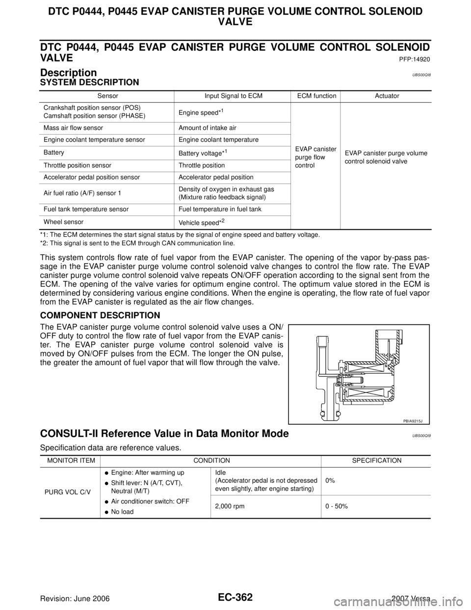
The EVAP canister purge volume control solenoid valve uses a ON/
OFF duty to control the flow rate of fuel vapor from the EVAP canis-
ter. The EVAP canister purge volume control solenoid valve is
moved by ON/OFF pulses from the ECM. The longer the ON pulse,
the greater the amount of fuel vapor that will flow through the valve.
CONSULT-II Reference Value in Data Monitor ModeUBS00QI9
Specification data are reference values.
Sensor Input Signal to ECM ECM function Actuator
Crankshaft position sensor (POS)
Camshaft position sensor (PHASE)Engine speed*
1
EVAP canister
purge flow
controlEVAP canister purge volume
control solenoid valve Mass air flow sensor Amount of intake air
Engine coolant temperature sensor Engine coolant temperature
Battery
Battery voltage*1
Throttle position sensor Throttle position
Accelerator pedal position sensor Accelerator pedal position
Air fuel ratio (A/F) sensor 1Density of oxygen in exhaust gas
(Mixture ratio feedback signal)
Fuel tank temperature sensor Fuel temperature in fuel tank
Wheel sensor
Vehicle speed*
2
PBIA9215J
MONITOR ITEM CONDITION SPECIFICATION
PURG VOL C/V
�Engine: After warming up
�Shift lever: N (A/T, CVT),
Neutral (M/T)
�Air conditioner switch: OFF
�No loadIdle
(Accelerator pedal is not depressed
even slightly, after engine starting)0%
2,000 rpm 0 - 50%
Page 1709 of 2896

EC-540Revision: June 2006
DTC P2A00 A/F SENSOR 1
2007 Versa
DTC P2A00 A/F SENSOR 1PFP:22693
Component DescriptionUBS00QNP
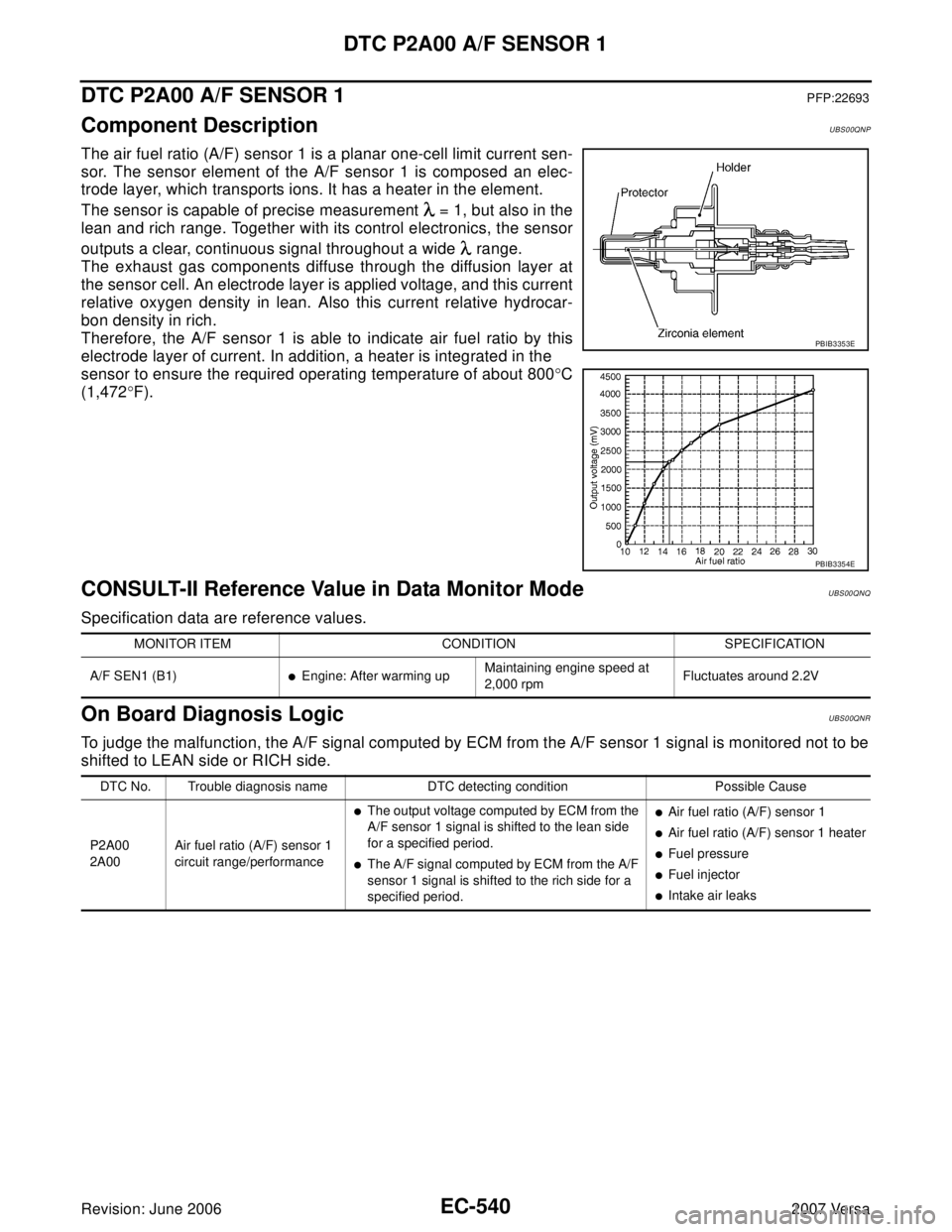
The air fuel ratio (A/F) sensor 1 is a planar one-cell limit current sen-
sor. The sensor element of the A/F sensor 1 is composed an elec-
trode layer, which transports ions. It has a heater in the element.
The sensor is capable of precise measurement = 1, but also in the
lean and rich range. Together with its control electronics, the sensor
outputs a clear, continuous signal throughout a wide range.
The exhaust gas components diffuse through the diffusion layer at
the sensor cell. An electrode layer is applied voltage, and this current
relative oxygen density in lean. Also this current relative hydrocar-
bon density in rich.
Therefore, the A/F sensor 1 is able to indicate air fuel ratio by this
electrode layer of current. In addition, a heater is integrated in the
sensor to ensure the required operating temperature of about 800°C
(1,472°F).
CONSULT-II Reference Value in Data Monitor ModeUBS00QNQ
Specification data are reference values.
On Board Diagnosis LogicUBS00QNR
To judge the malfunction, the A/F signal computed by ECM from the A/F sensor 1 signal is monitored not to be
shifted to LEAN side or RICH side.
PBIB3353E
PBIB3354E
MONITOR ITEM CONDITION SPECIFICATION
A/F SEN1 (B1)
�Engine: After warming upMaintaining engine speed at
2,000 rpmFluctuates around 2.2V
DTC No. Trouble diagnosis name DTC detecting condition Possible Cause
P2A00
2A00Air fuel ratio (A/F) sensor 1
circuit range/performance
�The output voltage computed by ECM from the
A/F sensor 1 signal is shifted to the lean side
for a specified period.
�The A/F signal computed by ECM from the A/F
sensor 1 signal is shifted to the rich side for a
specified period.
�Air fuel ratio (A/F) sensor 1
�Air fuel ratio (A/F) sensor 1 heater
�Fuel pressure
�Fuel injector
�Intake air leaks
Page 1763 of 2896

EC-594Revision: June 2006
SERVICE DATA AND SPECIFICATIONS (SDS)
2007 Versa
SERVICE DATA AND SPECIFICATIONS (SDS)PFP:00030
Fuel PressureUBS00PUA
Idle Speed and Ignition TimingUBS00PUB
*: Under the following conditions:
�Air conditioner switch: OFF
�Electric load: OFF (Lights, heater fan & rear window defogger)
�Steering wheel: Kept in straight-ahead position
Calculated Load ValueUBS00PUC
Mass Air Flow SensorUBS00PUD
*: Engine is warmed up to normal operating temperature and running under no load.
Intake Air Temperature SensorUBS00PUE
Engine Coolant Temperature SensorUBS00PUF
Air Fuel Ratio (A/F) Sensor 1 HeaterUBS00PUG
Heated Oxygen sensor 2 HeaterUBS00PUH
Crankshaft Position Sensor (POS)UBS00PUI
Refer to EC-326, "Component Inspection" .
Fuel pressure at idle
Approximately 350 kPa (3.57 kg/cm2 , 51 psi)
Target idle speedA/T No load* (in P or N position)
700 ± 50 rpm CVT No load* (In P or N position)
M/T No load* (in Neutral position)
Air conditioner: ONA/T In P or N position
700 rpm or more CVT In P or N position
M/T In Neutral position
Ignition timingA/T In P or N position
13 ± 5° BTDC CVT In P or N position
M/T In Neutral position
Calculated load value% (Using CONSULT-II or GST)
At idle10 - 35
At 2,500 rpm10 - 35
Supply voltageBattery voltage (11 - 14V)
Output voltage at idle1.0 - 1.3*V
Mass air flow (Using CONSULT-II or GST)1.0 - 4.0 g·m/sec at idle*
2.0 - 10.0 g·m/sec at 2,500 rpm*
Temperature °C (°F) Resistance kΩ
25 (77)1.800 - 2.200
Temperature °C (°F) Resistance kΩ
20 (68)2.1 - 2.9
50 (122)0.68 - 1.00
90 (194)0.236 - 0.260
Resistance [at 25°C (77°F)] 1.8 - 2.44Ω
Resistance [at 25°C (77°F)] 3.4 - 4.4Ω
Page 1817 of 2896
EM-8Revision: June 2006
PREPARATION
2007 Versa
ST16610001
(J-23907)
Pilot bushing pullerRemoving crankshaft pilot bushing
KV11103000
(—)
Pulley pullerRemoving crankshaft pulley
KV991J0050
(J-44626)
Air fuel sensor SocketLoosening or tightening air fuel ratio A/F
sensor
a: 22 mm (0.87 in)
KV10114400
(J-38365)
Heated oxygen sensor wrenchLoosening or tightening rear heated oxy-
gen sensor
a: 22 mm (0.87 in)
KV11105210
(J-44716)
Stopper plateSecuring diveplate and flywheel
KV10115600
(J-38958)
Valve oil seal driftInstalling valve oil seal
Use side A.
a: 20 (0.79) dia
b: 13 (0.51) dia.
c: 10.3 (0.406) dia
d: 8 (0.31) dia.
e: 10.7 (0.421)
f: 5 (0.20)
KV10115801
(—)
Oil filter wrenchRemoving and installing oil filter
a: 64.3 mm (2.531 in) Tool number
(Kent-Moore No.)
Tool nameDescription
NT045
NT676
LBIA0444E
NT636
ZZA0009D
S-NT603
S-NT375
Page 1819 of 2896
EM-10Revision: June 2006
PREPARATION
2007 Versa
Valve guide reamer (1): Reaming valve guide inner hole
(2): Reaming hole for oversize valve guide
(J-43897-18)
(J-43897-12)
Oxygen sensor thread cleanerReconditioning the exhaust system threads
before installing a new oxygen sensor (Use
with anti-seize lubricant shown below.)
a: J-43897-18 (18 mm dia.) for zirconia ox-
ygen sensor
b: J-43897-12 (12 mm dia.) for titania oxy-
gen sensor
Anti-seize lubricant (Permatex 133AR
or equivalent meeting MIL specifica-
tion MIL-A-907)Lubricating oxygen sensor thread cleaning
tool when reconditioning exhaust system
threads
E20 Torx® Socket
(J-45816)Removing and installing drive plate and fly-
wheel bolts (Kent-Moore No.)
Tool nameDescription
PBIC4013E
AEM488
AEM489
LBIA0285E
Page 1927 of 2896
EX-2Revision: June 2006
PREPARATION
2007 Versa
PREPARATIONPFP:00002
Special Service ToolsEBS00TSO
Commercial Service ToolsEBS00TSP
Tool number
Tool nameDescription
KV10114400
(J-38365)
Heated oxygen sensor wrenchLoosening or tightening heated oxygen sen-
sor
a: 22 mm (0.87 in)
NT636
Tool nameDescription
Heated oxygen sensor thread cleaner Reconditioning the exhaust system threads
before installing a new heated oxygen sensor
(Use with anti-seize lubricant shown below.)
a: 18 mm (0.71 in) dia. for zirconia heated
oxygen sensor
b: 12 mm (0.47 in) dia. for titania heated ox-
ygen sensor
Anti-seize lubricant (Permatex 133AR
or equivalent meeting MIL specifica-
tion MIL-A-907)Lubricating heated oxygen sensor thread
cleaner when reconditioning exhaust system
threads
AEM488
AEM489
Page 1928 of 2896
EXHAUST SYSTEM
EX-3
C
D
E
F
G
H
I
J
K
L
MA
EX
Revision: June 20062007 Versa
EXHAUST SYSTEMPFP:20100
Checking Exhaust SystemEBS00TSQ
Check exhaust pipes, muffler and mounting for improper attachment,
leaks, cracks, damage or deterioration.
�If necessary, repair or replace damaged parts.
ComponentsEBS00TSR
SM A211 A
1. Main muffler 2. Mounting rubber 3. Ring gasket
4. Center muffler 5. Mounting rubber 6. Spring
7. Seal bearing 8. Heated oxygen sensor 2 9. Exhaust front tube
10. Seal bearing 11. Stud bolt 12. Spring
13. Ground cable
WBIA0768E
Page 1929 of 2896

EX-4Revision: June 2006
EXHAUST SYSTEM
2007 Versa
Removal and InstallationEBS00TSS
REMOVAL
CAUTION:
�Be sure to use genuine NISSAN exhaust system parts or equivalents which are specially designed
for heat resistance, corrosion resistance and shape.
�Perform the operation with the exhaust system fully cooled down because the system will be hot
just after the engine stops.
�Be careful not to cut your hand on heat insulator edge.
1. Disconnect harness connector of heated oxygen sensor 2.
�Using Tool, remove heated oxygen sensor 2.
CAUTION:
Be careful not to damage heated oxygen sensor 2.
a.2. Disconnect each joint and mounting rubber.
INSTALLATION
Installation is in the reverse order of removal.
CAUTION:
�Always replace exhaust gaskets and seal bearings with new ones when installing.
�Discard any heated oxygen sensor 2 which has been dropped from a height of more than 0.5 m
(19.7 in) onto a hard surface such as a concrete floor; use a new one.
�Before installing a new heated oxygen sensor 2, clean exhaust system threads using the heated
oxygen sensor thread cleaner and apply anti-seize lubricant (commercial service tool).
�Do not over tighten heated oxygen sensor 2. Doing so may cause damage to the heated oxygen
sensor 2, resulting in the “MIL” coming on.
�Remove deposits from the sealing surface of each connection. Connect them securely to avoid
exhaust leakage.
�Temporarily tighten nuts on the exhaust manifold side and bolts on the vehicle side. Check each
part for unusual interference, and then tighten them to the specified torque.
�When installing each mounting rubber, avoid twisting or unusual extension in up/down and right/
left directions.
Exhaust Manifold to Exhaust Front Tube
1. Securely insert seal bearing (2) into exhaust manifold (1) side in
the direction shown.
�Exhaust front tube (5)
CAUTION:
Be careful not to damage seal bearing surface when install-
ing.
2. Install spring (3), tighten nut (4).
�Be careful that the stud bolt nut does not interfere with the
flanged area ( ).
�Make sure the spring (3) sits properly on the flange surface by
align it to the locator dimples.Tool number : KV10114400 (J-38365)PBIC3797E