Page 1416 of 2896
DTC P0133 A/F SENSOR 1
EC-247
C
D
E
F
G
H
I
J
K
L
MA
EC
Revision: June 20062007 Versa
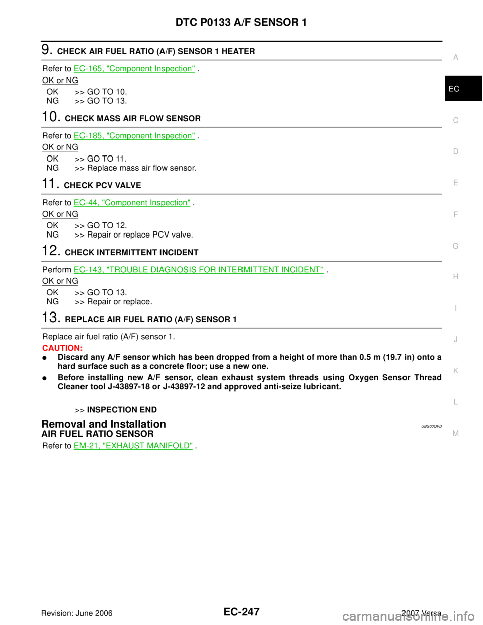
9. CHECK AIR FUEL RATIO (A/F) SENSOR 1 HEATER
Refer to EC-165, "
Component Inspection" .
OK or NG
OK >> GO TO 10.
NG >> GO TO 13.
10. CHECK MASS AIR FLOW SENSOR
Refer to EC-185, "
Component Inspection" .
OK or NG
OK >> GO TO 11.
NG >> Replace mass air flow sensor.
11 . CHECK PCV VALVE
Refer to EC-44, "
Component Inspection" .
OK or NG
OK >> GO TO 12.
NG >> Repair or replace PCV valve.
12. CHECK INTERMITTENT INCIDENT
Perform EC-143, "
TROUBLE DIAGNOSIS FOR INTERMITTENT INCIDENT" .
OK or NG
OK >> GO TO 13.
NG >> Repair or replace.
13. REPLACE AIR FUEL RATIO (A/F) SENSOR 1
Replace air fuel ratio (A/F) sensor 1.
CAUTION:
�Discard any A/F sensor which has been dropped from a height of more than 0.5 m (19.7 in) onto a
hard surface such as a concrete floor; use a new one.
�Before installing new A/F sensor, clean exhaust system threads using Oxygen Sensor Thread
Cleaner tool J-43897-18 or J-43897-12 and approved anti-seize lubricant.
>>INSPECTION END
Removal and InstallationUBS00QFD
AIR FUEL RATIO SENSOR
Refer to EM-21, "EXHAUST MANIFOLD" .
Page 1421 of 2896
EC-252Revision: June 2006
DTC P0137 HO2S2
2007 Versa
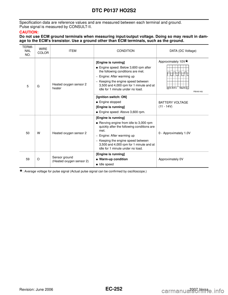
Specification data are reference values and are measured between each terminal and ground.
Pulse signal is measured by CONSULT-II.
CAUTION:
Do not use ECM ground terminals when measuring input/output voltage. Doing so may result in dam-
age to the ECM's transistor. Use a ground other than ECM terminals, such as the ground.
: Average voltage for pulse signal (Actual pulse signal can be confirmed by oscilloscope.) TERMI-
NAL
NO.WIRE
COLORITEM CONDITION DATA (DC Voltage)
5GHeated oxygen sensor 2
heater[Engine is running]
�Engine speed: Below 3,600 rpm after
the following conditions are met.
–Engine: After warming up
–Keeping the engine speed between
3,500 and 4,000 rpm for 1 minute and at
idle for 1 minute under no load.Approximately 10V
[Ignition switch: ON]
�Engine stopped
[Engine is running]
�Engine speed: Above 3,600 rpm.BATTERY VOLTAGE
(11 - 14V)
50 W Heated oxygen sensor 2[Engine is running]
�Revving engine from idle to 3,000 rpm
quickly after the following conditions are
met.
–Engine: After warming up
–Keeping the engine speed between
3,500 and 4,000 rpm for 1 minute and at
idle for 1 minute under no load.0 - Approximately 1.0V
59 OSensor ground
(Heated oxygen sensor 2)[Engine is running]
�Warm-up condition
�Idle speedApproximately 0V
PBIA8148J
Page 1430 of 2896
DTC P0138 HO2S2
EC-261
C
D
E
F
G
H
I
J
K
L
MA
EC
Revision: June 20062007 Versa
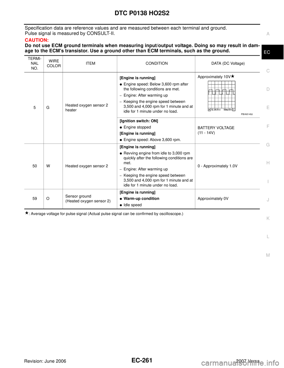
Specification data are reference values and are measured between each terminal and ground.
Pulse signal is measured by CONSULT-II.
CAUTION:
Do not use ECM ground terminals when measuring input/output voltage. Doing so may result in dam-
age to the ECM's transistor. Use a ground other than ECM terminals, such as the ground.
: Average voltage for pulse signal (Actual pulse signal can be confirmed by oscilloscope.) TERMI-
NAL
NO.WIRE
COLORITEM CONDITION DATA (DC Voltage)
5GHeated oxygen sensor 2
heater[Engine is running]
�Engine speed: Below 3,600 rpm after
the following conditions are met.
–Engine: After warming up
–Keeping the engine speed between
3,500 and 4,000 rpm for 1 minute and at
idle for 1 minute under no load.Approximately 10V
[Ignition switch: ON]
�Engine stopped
[Engine is running]
�Engine speed: Above 3,600 rpm.BATTERY VOLTAGE
(11 - 14V)
50 W Heated oxygen sensor 2[Engine is running]
�Revving engine from idle to 3,000 rpm
quickly after the following conditions are
met.
–Engine: After warming up
–Keeping the engine speed between
3,500 and 4,000 rpm for 1 minute and at
idle for 1 minute under no load.0 - Approximately 1.0V
59 OSensor ground
(Heated oxygen sensor 2)[Engine is running]
�Warm-up condition
�Idle speedApproximately 0V
PBIA8148J
Page 1440 of 2896
DTC P0139 HO2S2
EC-271
C
D
E
F
G
H
I
J
K
L
MA
EC
Revision: June 20062007 Versa
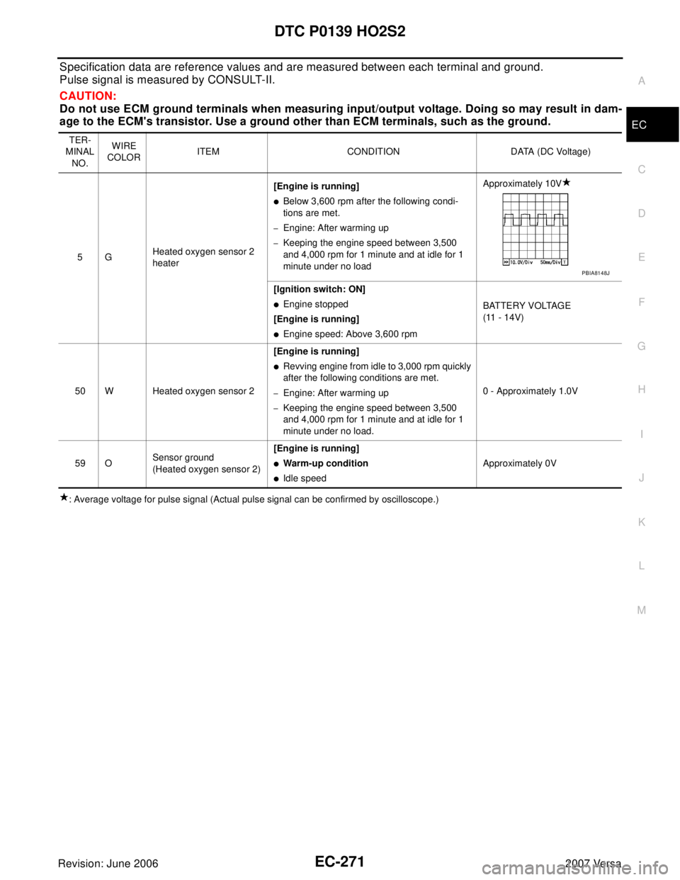
Specification data are reference values and are measured between each terminal and ground.
Pulse signal is measured by CONSULT-II.
CAUTION:
Do not use ECM ground terminals when measuring input/output voltage. Doing so may result in dam-
age to the ECM's transistor. Use a ground other than ECM terminals, such as the ground.
: Average voltage for pulse signal (Actual pulse signal can be confirmed by oscilloscope.)TER-
MINAL
NO.WIRE
COLORITEM CONDITION DATA (DC Voltage)
5GHeated oxygen sensor 2
heater[Engine is running]
�Below 3,600 rpm after the following condi-
tions are met.
–Engine: After warming up
–Keeping the engine speed between 3,500
and 4,000 rpm for 1 minute and at idle for 1
minute under no loadApproximately 10V
[Ignition switch: ON]
�Engine stopped
[Engine is running]
�Engine speed: Above 3,600 rpmBATTERY VOLTAGE
(11 - 14V)
50 W Heated oxygen sensor 2[Engine is running]
�Revving engine from idle to 3,000 rpm quickly
after the following conditions are met.
–Engine: After warming up
–Keeping the engine speed between 3,500
and 4,000 rpm for 1 minute and at idle for 1
minute under no load.0 - Approximately 1.0V
59 OSensor ground
(Heated oxygen sensor 2)[Engine is running]
�Warm-up condition
�Idle speedApproximately 0V
PBIA8148J
Page 1448 of 2896
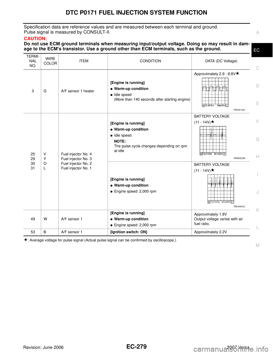
DTC P0171 FUEL INJECTION SYSTEM FUNCTION
EC-279
C
D
E
F
G
H
I
J
K
L
MA
EC
Revision: June 20062007 Versa
Specification data are reference values and are measured between each terminal and ground.
Pulse signal is measured by CONSULT-II.
CAUTION:
Do not use ECM ground terminals when measuring input/output voltage. Doing so may result in dam-
age to the ECM's transistor. Use a ground other than ECM terminals, such as the ground.
: Average voltage for pulse signal (Actual pulse signal can be confirmed by oscilloscope.) TERMI-
NAL
NO.WIRE
COLORITEM CONDITION DATA (DC Voltage)
3 G A/F sensor 1 heater[Engine is running]
�Warm-up condition
�Idle speed
(More than 140 seconds after starting engine)Approximately 2.9 - 8.8V
25
29
30
31V
Y
O
LFuel injector No. 4
Fuel injector No. 3
Fuel injector No. 2
Fuel injector No. 1[Engine is running]
�Warm-up condition
�Idle speed
NOTE:
The pulse cycle changes depending on rpm
at idleBATTERY VOLTAGE
(11 - 14V)
[Engine is running]
�Warm-up condition
�Engine speed: 2,000 rpmBATTERY VOLTAGE
(11 - 14V)
49 W A/F sensor 1[Engine is running]
�Warm-up condition
�Engine speed: 2,000 rpmApproximately 1.8V
Output voltage varies with air
fuel ratio.
53 B A/F sensor 1[Ignition switch: ON]Approximately 2.2V
PBIA8148J
PBIB0529E
PBIA4943J
Page 1456 of 2896
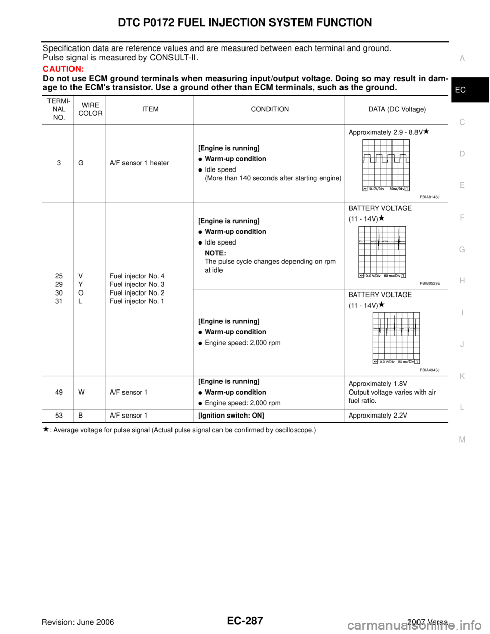
DTC P0172 FUEL INJECTION SYSTEM FUNCTION
EC-287
C
D
E
F
G
H
I
J
K
L
MA
EC
Revision: June 20062007 Versa
Specification data are reference values and are measured between each terminal and ground.
Pulse signal is measured by CONSULT-II.
CAUTION:
Do not use ECM ground terminals when measuring input/output voltage. Doing so may result in dam-
age to the ECM's transistor. Use a ground other than ECM terminals, such as the ground.
: Average voltage for pulse signal (Actual pulse signal can be confirmed by oscilloscope.) TERMI-
NAL
NO.WIRE
COLORITEM CONDITION DATA (DC Voltage)
3 G A/F sensor 1 heater[Engine is running]
�Warm-up condition
�Idle speed
(More than 140 seconds after starting engine)Approximately 2.9 - 8.8V
25
29
30
31V
Y
O
LFuel injector No. 4
Fuel injector No. 3
Fuel injector No. 2
Fuel injector No. 1[Engine is running]
�Warm-up condition
�Idle speed
NOTE:
The pulse cycle changes depending on rpm
at idleBATTERY VOLTAGE
(11 - 14V)
[Engine is running]
�Warm-up condition
�Engine speed: 2,000 rpmBATTERY VOLTAGE
(11 - 14V)
49 W A/F sensor 1[Engine is running]
�Warm-up condition
�Engine speed: 2,000 rpmApproximately 1.8V
Output voltage varies with air
fuel ratio.
53 B A/F sensor 1[Ignition switch: ON]Approximately 2.2V
PBIA8148J
PBIB0529E
PBIA4943J
Page 1482 of 2896
DTC P0300 - P0304 MULTIPLE CYLINDER MISFIRE, NO. 1 - 4 CYLINDER MIS-
FIRE
EC-313
C
D
E
F
G
H
I
J
K
L
MA
EC
Revision: June 20062007 Versa
12. CHECK IGNITION TIMING
Check the following items. Refer to EC-70, "
Basic Inspection" .
OK or NG
OK >> GO TO 13.
NG >> Follow the EC-70, "
Basic Inspection" .
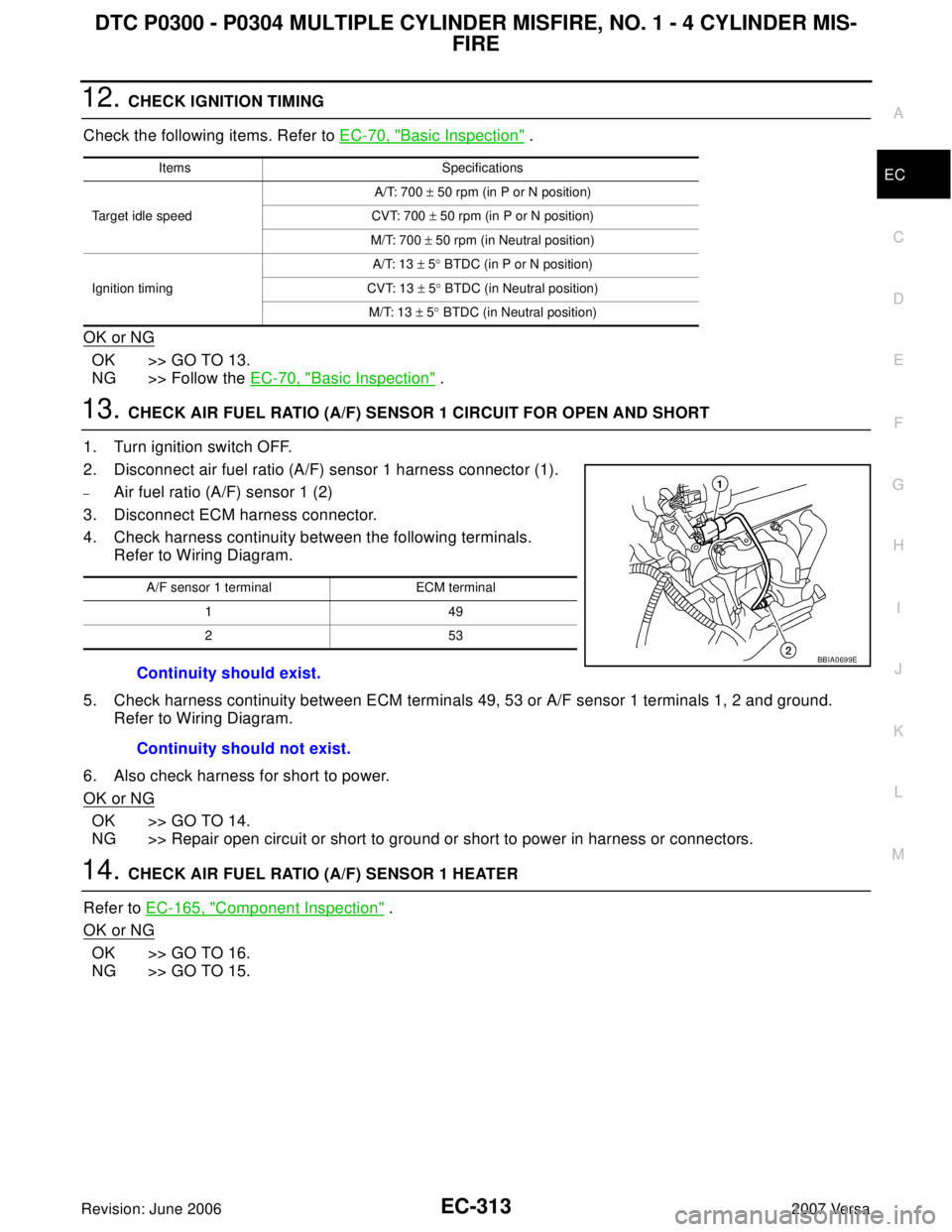
13. CHECK AIR FUEL RATIO (A/F) SENSOR 1 CIRCUIT FOR OPEN AND SHORT
1. Turn ignition switch OFF.
2. Disconnect air fuel ratio (A/F) sensor 1 harness connector (1).
–Air fuel ratio (A/F) sensor 1 (2)
3. Disconnect ECM harness connector.
4. Check harness continuity between the following terminals.
Refer to Wiring Diagram.
5. Check harness continuity between ECM terminals 49, 53 or A/F sensor 1 terminals 1, 2 and ground.
Refer to Wiring Diagram.
6. Also check harness for short to power.
OK or NG
OK >> GO TO 14.
NG >> Repair open circuit or short to ground or short to power in harness or connectors.
14. CHECK AIR FUEL RATIO (A/F) SENSOR 1 HEATER
Refer to EC-165, "
Component Inspection" .
OK or NG
OK >> GO TO 16.
NG >> GO TO 15.
Items Specifications
Target idle speedA/T: 700 ± 50 rpm (in P or N position)
CVT: 700 ± 50 rpm (in P or N position)
M/T: 700 ± 50 rpm (in Neutral position)
Ignition timingA/T: 13 ± 5° BTDC (in P or N position)
CVT: 13 ± 5° BTDC (in Neutral position)
M/T: 13 ± 5° BTDC (in Neutral position)
A/F sensor 1 terminal ECM terminal
149
253
Continuity should exist.
Continuity should not exist.
BBIA0699E
Page 1611 of 2896
EC-442Revision: June 2006
DTC P1148 CLOSED LOOP CONTROL
2007 Versa
DTC P1148 CLOSED LOOP CONTROLPFP:22690
On Board Diagnosis LogicUBS00QKS
This self-diagnosis has the one trip detection logic.
NOTE:
DTC P1148 is displayed with another DTC for air fuel ratio (A/F) sensor 1.
Perform the trouble diagnosis for the corresponding DTC.
DTC No. Trouble diagnosis name DTC detecting condition Possible cause
P1148
11 4 8Closed loop control
functionThe closed loop control function does not oper-
ate even when vehicle is driving in the speci-
fied condition.
�Harness or connectors
[Air fuel ratio (A/F) sensor 1 circuit is
open or shorted.]
�Air fuel ratio (A/F) sensor 1
�Air fuel ratio (A/F) sensor 1 heater