Page 2104 of 2896
IP-4
SQUEAK AND RATTLE TROUBLE DIAGNOSES
Revision: June 20062007 Versa
SQUEAK AND RATTLE TROUBLE DIAGNOSESPFP:00000
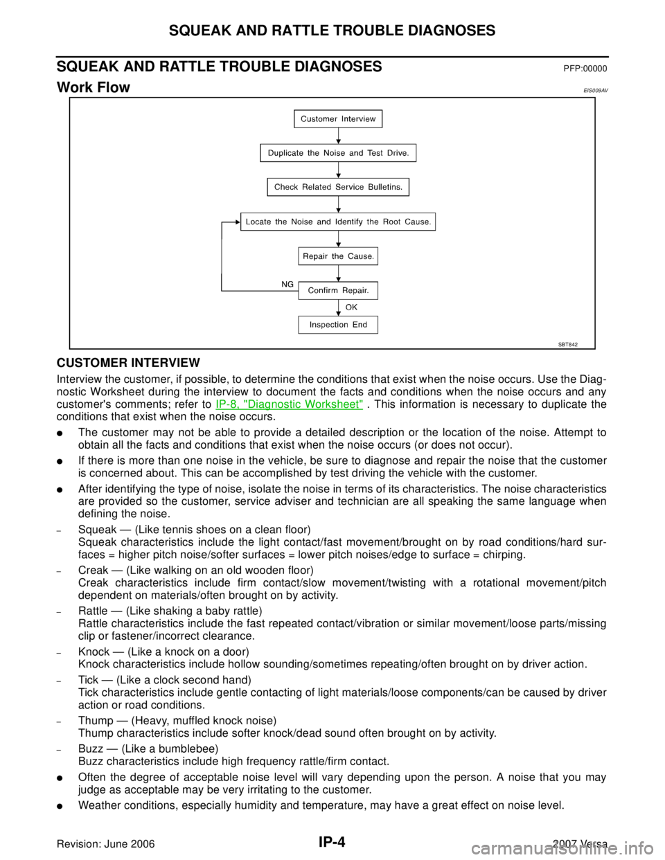
Work FlowEIS0 09 AV
CUSTOMER INTERVIEW
Interview the customer, if possible, to determine the conditions that exist when the noise occurs. Use the Diag-
nostic Worksheet during the interview to document the facts and conditions when the noise occurs and any
customer's comments; refer to IP-8, "
Diagnostic Worksheet" . This information is necessary to duplicate the
conditions that exist when the noise occurs.
�The customer may not be able to provide a detailed description or the location of the noise. Attempt to
obtain all the facts and conditions that exist when the noise occurs (or does not occur).
�If there is more than one noise in the vehicle, be sure to diagnose and repair the noise that the customer
is concerned about. This can be accomplished by test driving the vehicle with the customer.
�After identifying the type of noise, isolate the noise in terms of its characteristics. The noise characteristics
are provided so the customer, service adviser and technician are all speaking the same language when
defining the noise.
–Squeak — (Like tennis shoes on a clean floor)
Squeak characteristics include the light contact/fast movement/brought on by road conditions/hard sur-
faces = higher pitch noise/softer surfaces = lower pitch noises/edge to surface = chirping.
–Creak — (Like walking on an old wooden floor)
Creak characteristics include firm contact/slow movement/twisting with a rotational movement/pitch
dependent on materials/often brought on by activity.
–Rattle — (Like shaking a baby rattle)
Rattle characteristics include the fast repeated contact/vibration or similar movement/loose parts/missing
clip or fastener/incorrect clearance.
–Knock — (Like a knock on a door)
Knock characteristics include hollow sounding/sometimes repeating/often brought on by driver action.
–Tick — (Like a clock second hand)
Tick characteristics include gentle contacting of light materials/loose components/can be caused by driver
action or road conditions.
–Thump — (Heavy, muffled knock noise)
Thump characteristics include softer knock/dead sound often brought on by activity.
–Buzz — (Like a bumblebee)
Buzz characteristics include high frequency rattle/firm contact.
�Often the degree of acceptable noise level will vary depending upon the person. A noise that you may
judge as acceptable may be very irritating to the customer.
�Weather conditions, especially humidity and temperature, may have a great effect on noise level.
SBT 8 42
Page 2233 of 2896
HEADLAMP (FOR USA)
LT-25
C
D
E
F
G
H
I
J
L
MA
B
LT
Revision: June 20062007 Versa
Bulb ReplacementEKS00IMH
CAUTION:
After installing bulb, be sure to install plastic cap and bulb socket securely to ensure watertightness.
HEADLAMP (HIGH/LOW)
1. Turn lighting switch OFF.
2. Remove the headlamp. Refer to LT- 2 5 , "
Removal and Installation" .
3. Remove back cover.
4. Unlock retaining spring and remove bulb from headlamp.
PARKING (CLEARANCE) LAMP
1. Turn lighting switch OFF.
2. Remove the headlamp. Refer to LT- 2 5 , "
Removal and Installation" .
3. Turn bulb socket counterclockwise and unlock it.
4. Remove bulb from its socket.
FRONT TURN SIGNAL LAMP
1. Turn lighting switch OFF.
2. Remove the headlamp. Refer to LT- 2 5 , "
Removal and Installation" .
3. Turn bulb socket counterclockwise and unlock it.
4. Remove bulb from its socket.
Removal and InstallationEKS00IMI
REMOVAL
1. Disconnect the negative battery terminal.
2. Remove front bumper fascia. Refer to EI-14, "
FRONT BUMPER" .
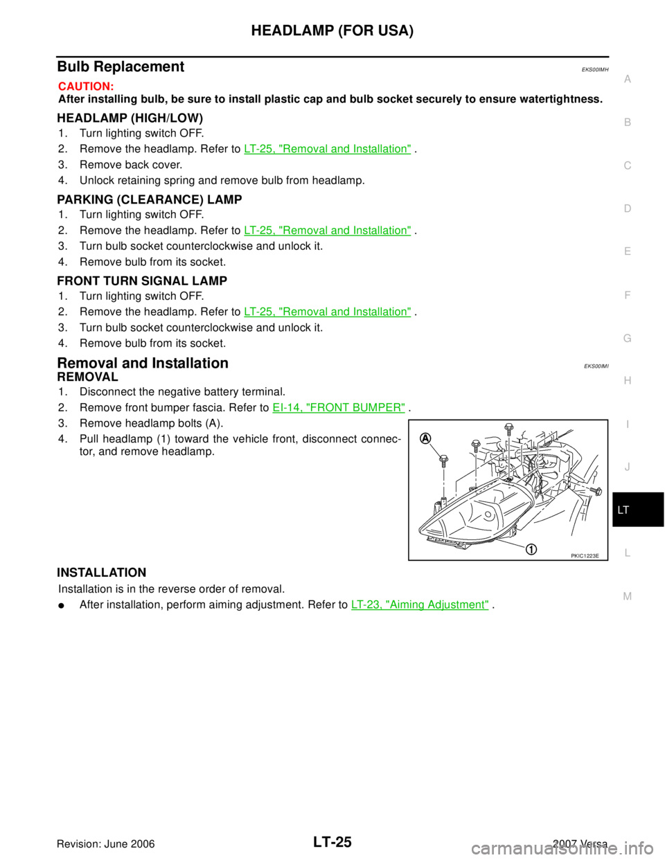
3. Remove headlamp bolts (A).
4. Pull headlamp (1) toward the vehicle front, disconnect connec-
tor, and remove headlamp.
INSTALLATION
Installation is in the reverse order of removal.
�After installation, perform aiming adjustment. Refer to LT-23, "Aiming Adjustment" .
PKIC1223E
Page 2234 of 2896
LT-26
HEADLAMP (FOR USA)
Revision: June 20062007 Versa
Disassembly and AssemblyEKS00IMJ
DISASSEMBLY
1. Remove back cover.
2. Unlock retaining spring and remove bulb (High/Low).
3. Turn parking (clearance) lamp bulb socket counterclockwise and unlock it.
4. Remove parking (clearance) lamp bulb from its socket.
5. Turn front turn signal lamp bulb socket counterclockwise and unlock it.
6. Remove front turn signal lamp bulb from its socket.
7. Remove the bumper stay.
ASSEMBLY
Assembly is in the reverse order of disassembly.
CAUTION:
�After installing bulb, be sure to install plastic cap securely to insure water tight seal.
1. Retaining spring 2. Parking (clearance) lamp bulb 3. Parking (clearance) lamp bulb socket
4. Halogen bulb (High/Low) 5. Back cover 6. Front turn signal lamp bulb socket
7. Front turn signal lamp bulb 8. Headlamp housing assembly 9. Bumper stay
A. Screw
WKIA5418E
Page 2247 of 2896
HEADLAMP (FOR CANADA) - DAYTIME LIGHT SYSTEM -
LT-39
C
D
E
F
G
H
I
J
L
MA
B
LT
Revision: June 20062007 Versa
Bulb ReplacementEKS00IM5
CAUTION:
After installing bulb, be sure to install plastic cap and bulb socket securely to ensure watertightness.
HEADLAMP (HIGH/LOW)
1. Turn lighting switch OFF.
2. Remove the headlamp. Refer to LT- 2 5 , "
Removal and Installation" .
3. Remove back cover.
4. Unlock retaining spring and remove bulb from headlamp.
PARKING (CLEARANCE) LAMP
1. Turn lighting switch OFF.
2. Remove the headlamp. Refer to LT- 2 5 , "
Removal and Installation" .
3. Turn bulb socket counterclockwise and unlock it.
4. Remove bulb from its socket.
FRONT TURN SIGNAL LAMP
1. Turn lighting switch OFF.
2. Remove the headlamp. Refer to LT- 2 5 , "
Removal and Installation" .
3. Turn bulb socket counterclockwise and unlock it.
4. Remove bulb from its socket.
Removal and InstallationEKS00IM6
REMOVAL
1. Disconnect the negative battery terminal.
2. Remove front bumper fascia. Refer to EI-14, "
FRONT BUMPER" .
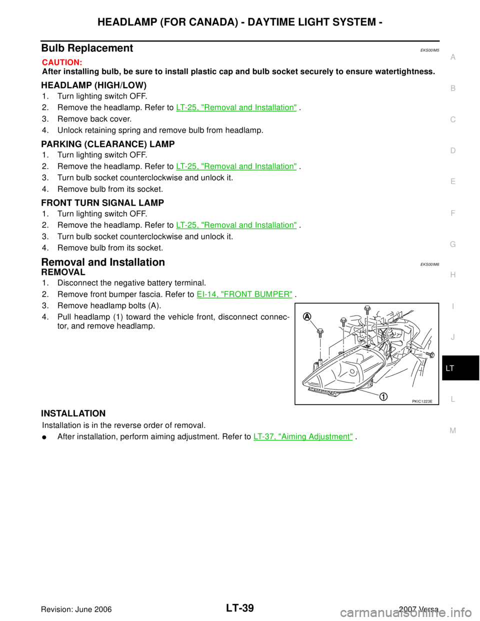
3. Remove headlamp bolts (A).
4. Pull headlamp (1) toward the vehicle front, disconnect connec-
tor, and remove headlamp.
INSTALLATION
Installation is in the reverse order of removal.
�After installation, perform aiming adjustment. Refer to LT-37, "Aiming Adjustment" .
PKIC1223E
Page 2248 of 2896
LT-40
HEADLAMP (FOR CANADA) - DAYTIME LIGHT SYSTEM -
Revision: June 20062007 Versa
Disassembly and AssemblyEKS00IM7
DISASSEMBLY
1. Remove back cover.
2. Unlock retaining spring and remove bulb (High/Low).
3. Turn parking (clearance) lamp bulb socket counterclockwise and unlock it.
4. Remove parking (clearance) lamp bulb from its socket.
5. Turn front turn signal lamp bulb socket counterclockwise and unlock it.
6. Remove front turn signal lamp bulb from its socket.
7. Remove the bumper stay.
ASSEMBLY
Assembly is in the reverse order of disassembly.
CAUTION:
�After installing bulb, be sure to install plastic cap securely to insure water tight seal.
1. Retaining spring 2. Parking (clearance) lamp bulb 3. Parking (clearance) lamp bulb socket
4. Halogen bulb (High/Low) 5. Back cover 6. Front turn signal lamp bulb socket
7. Front turn signal lamp bulb 8. Headlamp housing assembly 9. Bumper stay
A. Screw
WKIA5418E
Page 2257 of 2896
FRONT FOG LAMP
LT-49
C
D
E
F
G
H
I
J
L
MA
B
LT
Revision: June 20062007 Versa
Aiming AdjustmentEKS00HXJ
The front fog lamp is a semi-sealed beam type which uses a replaceable halogen bulb. Before performing
aiming adjustment, make sure of the following.
�Keep all tires inflated to correct pressure.
�Place vehicle on level surface.
�Set that there is no-load in vehicle other than the driver (or equivalent weight placed in driver’s position).
Coolant, engine oil filled up to correct level and full fuel tank.
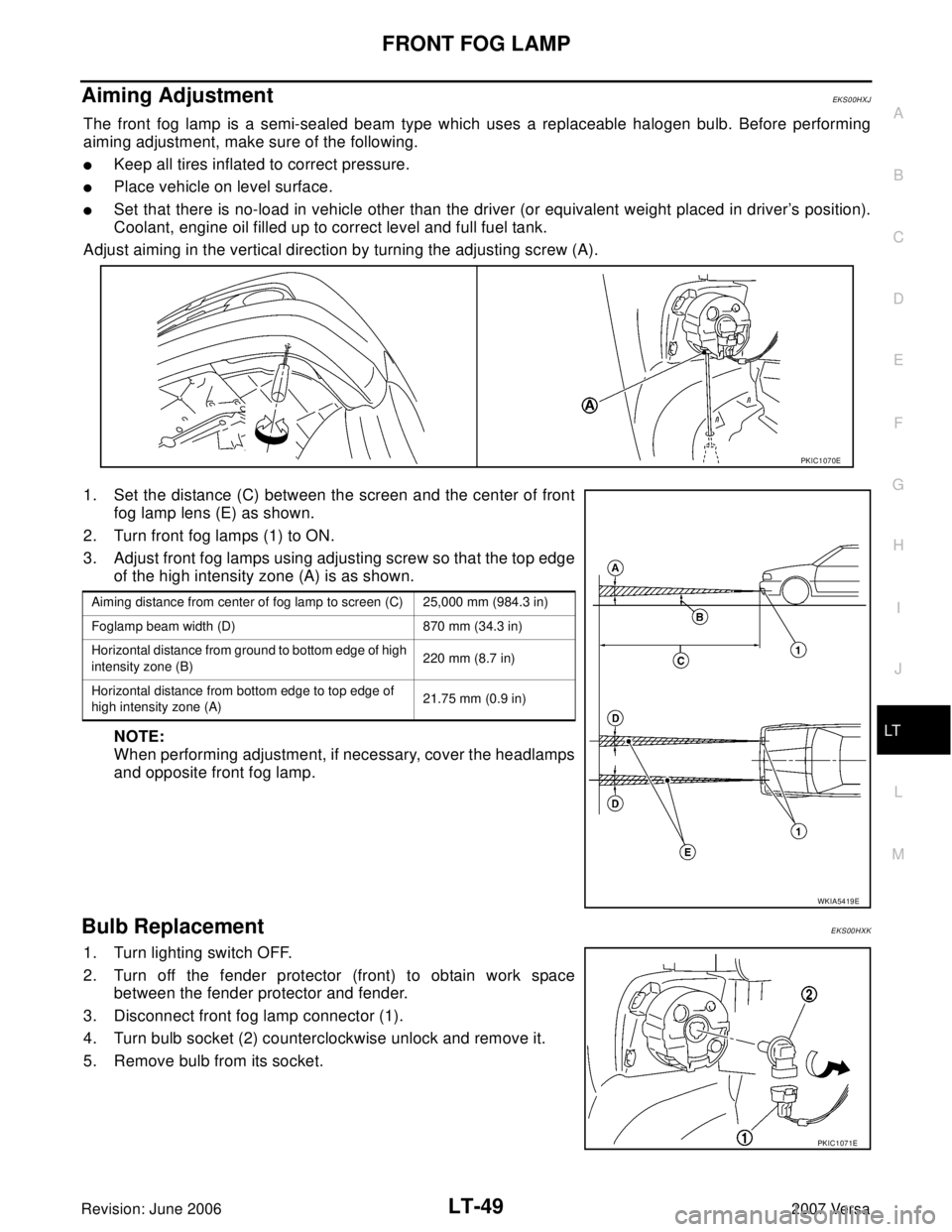
Adjust aiming in the vertical direction by turning the adjusting screw (A).
1. Set the distance (C) between the screen and the center of front
fog lamp lens (E) as shown.
2. Turn front fog lamps (1) to ON.
3. Adjust front fog lamps using adjusting screw so that the top edge
of the high intensity zone (A) is as shown.
NOTE:
When performing adjustment, if necessary, cover the headlamps
and opposite front fog lamp.
Bulb ReplacementEKS00HXK
1. Turn lighting switch OFF.
2. Turn off the fender protector (front) to obtain work space
between the fender protector and fender.
3. Disconnect front fog lamp connector (1).
4. Turn bulb socket (2) counterclockwise unlock and remove it.
5. Remove bulb from its socket.
PKIC1070E
Aiming distance from center of fog lamp to screen (C) 25,000 mm (984.3 in)
Foglamp beam width (D) 870 mm (34.3 in)
Horizontal distance from ground to bottom edge of high
intensity zone (B)220 mm (8.7 in)
Horizontal distance from bottom edge to top edge of
high intensity zone (A)21.75 mm (0.9 in)
WKIA5419E
PKIC1071E
Page 2294 of 2896
LT-86
PARKING, LICENSE PLATE AND TAIL LAMPS
Revision: June 20062007 Versa
Bulb ReplacementEKS00HZC
PA R K I N G L A M P
Refer to LT- 8 7 , "Bulb Replacement" .
LICENSE PLATE LAMP
1. Remove the license plate lamp. Refer to LT- 8 6 , "LICENSE PLATE LAMP" .
2. Turn bulb socket counterclockwise and unlock it.
3. Remove bulb from the socket.
4. Installation is in the reverse order of removal.
TA I L L A M P
Refer to LT- 8 7 , "Bulb Replacement" .
Removal and InstallationEKS00HZD
PA R K I N G L A M P
Refer to LT- 8 7 , "Removal and Installation" .
LICENSE PLATE LAMP
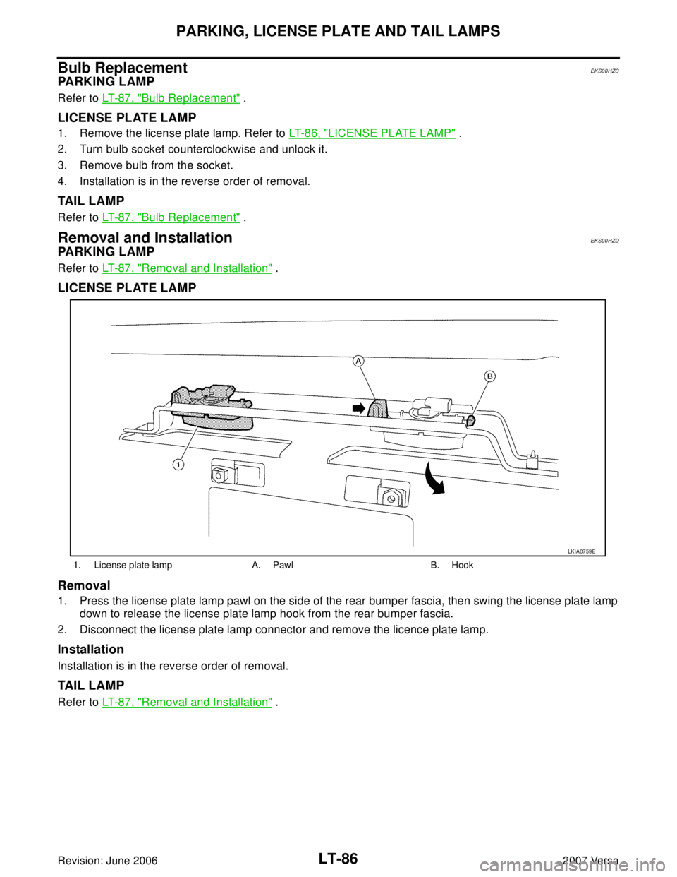
Removal
1. Press the license plate lamp pawl on the side of the rear bumper fascia, then swing the license plate lamp
down to release the license plate lamp hook from the rear bumper fascia.
2. Disconnect the license plate lamp connector and remove the licence plate lamp.
Installation
Installation is in the reverse order of removal.
TA I L L A M P
Refer to LT- 8 7 , "Removal and Installation" .
1. License plate lamp A. Pawl B. Hook
LKIA0759E
Page 2295 of 2896
REAR COMBINATION LAMP
LT-87
C
D
E
F
G
H
I
J
L
MA
B
LT
Revision: June 20062007 Versa
REAR COMBINATION LAMPPFP:26554
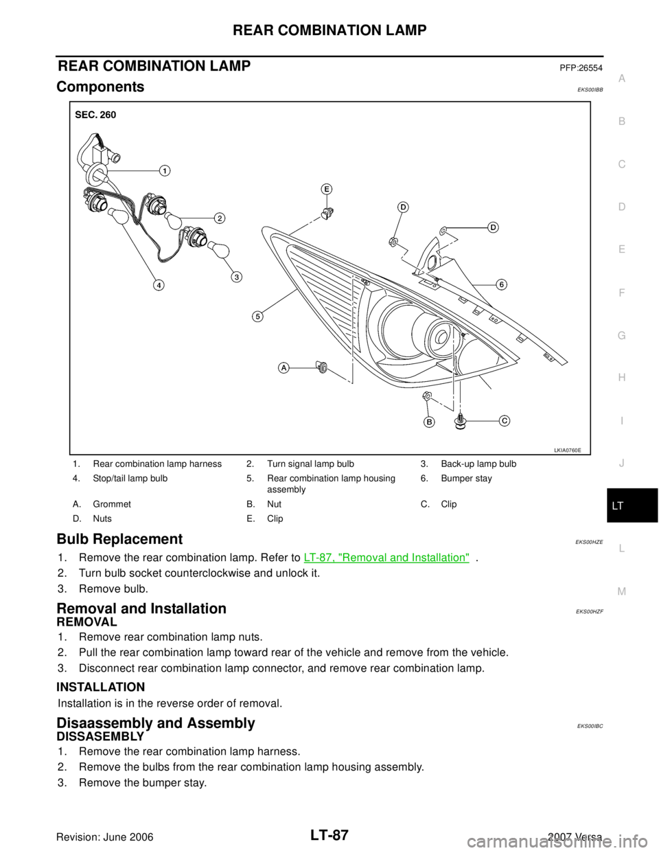
ComponentsEKS00IBB
Bulb ReplacementEKS00HZE
1. Remove the rear combination lamp. Refer to LT- 8 7 , "Removal and Installation" .
2. Turn bulb socket counterclockwise and unlock it.
3. Remove bulb.
Removal and InstallationEKS00HZF
REMOVAL
1. Remove rear combination lamp nuts.
2. Pull the rear combination lamp toward rear of the vehicle and remove from the vehicle.
3. Disconnect rear combination lamp connector, and remove rear combination lamp.
INSTALLATION
Installation is in the reverse order of removal.
Disaassembly and AssemblyEKS00IBC
DISSASEMBLY
1. Remove the rear combination lamp harness.
2. Remove the bulbs from the rear combination lamp housing assembly.
3. Remove the bumper stay.
1. Rear combination lamp harness 2. Turn signal lamp bulb 3. Back-up lamp bulb
4. Stop/tail lamp bulb 5. Rear combination lamp housing
assembly6. Bumper stay
A. Grommet B. Nut C. Clip
D. Nuts E. Clip
LKIA0760E