Page 790 of 2896
BRAKE PEDAL
BR-7
C
D
E
G
H
I
J
K
L
MA
B
BR
Revision: June 20062007 Versa
ADJUSTMENT
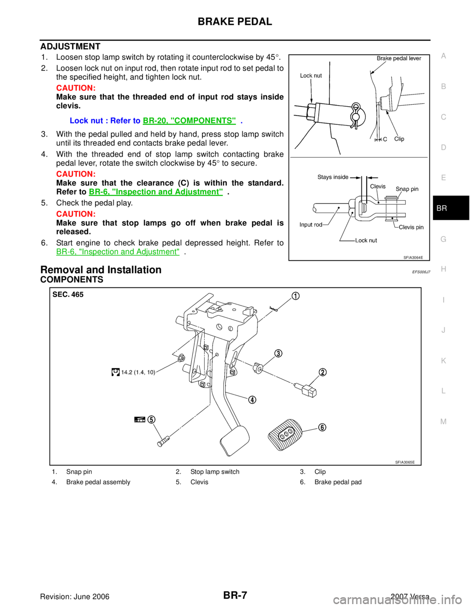
1. Loosen stop lamp switch by rotating it counterclockwise by 45°.
2. Loosen lock nut on input rod, then rotate input rod to set pedal to
the specified height, and tighten lock nut.
CAUTION:
Make sure that the threaded end of input rod stays inside
clevis.
3. With the pedal pulled and held by hand, press stop lamp switch
until its threaded end contacts brake pedal lever.
4. With the threaded end of stop lamp switch contacting brake
pedal lever, rotate the switch clockwise by 45° to secure.
CAUTION:
Make sure that the clearance (C) is within the standard.
Refer to BR-6, "
Inspection and Adjustment" .
5. Check the pedal play.
CAUTION:
Make sure that stop lamps go off when brake pedal is
released.
6. Start engine to check brake pedal depressed height. Refer to
BR-6, "
Inspection and Adjustment" .
Removal and InstallationEFS006J7
COMPONENTS
Lock nut : Refer to BR-20, "COMPONENTS" .
SFIA3064E
1. Snap pin 2. Stop lamp switch 3. Clip
4. Brake pedal assembly 5. Clevis 6. Brake pedal pad
SFIA3065E
Page 794 of 2896
BRAKE TUBE AND HOSE
BR-11
C
D
E
G
H
I
J
K
L
MA
B
BR
Revision: June 20062007 Versa
BRAKE TUBE AND HOSEPFP:46300
Hydraulic CircuitEFS006JB
CAUTION:
�All tubes and hoses must be free from excessive bending, twisting and pulling.
�Make sure there is no interference with other parts when turning steering both clockwise and
counterclockwise.
�Brake tubes and hoses are an important safety part. Always disassemble the parts and retighten
their fittings, if a brake fluid leak is detected. Replace applicable part with a new one, if damaged
part is detected.
�Be careful not to splash brake fluid on painted areas; it way cause paint damage. If brake fluid is
splashed on painted surfaces of body, immediately wipe them with cloth and then wash it away
with water.
�Do not bend or twist brake hose sharply, or strongly pull it.
�When removing components, cover brake line connections so that dirt, dust, or other foreign mat-
ters do not get in.
�Refill using recommended brake fluid. Refer to MA-11, "RECOMMENDED FLUIDS AND LUBRI-
CANTS" .
�Never reuse drained brake fluid.
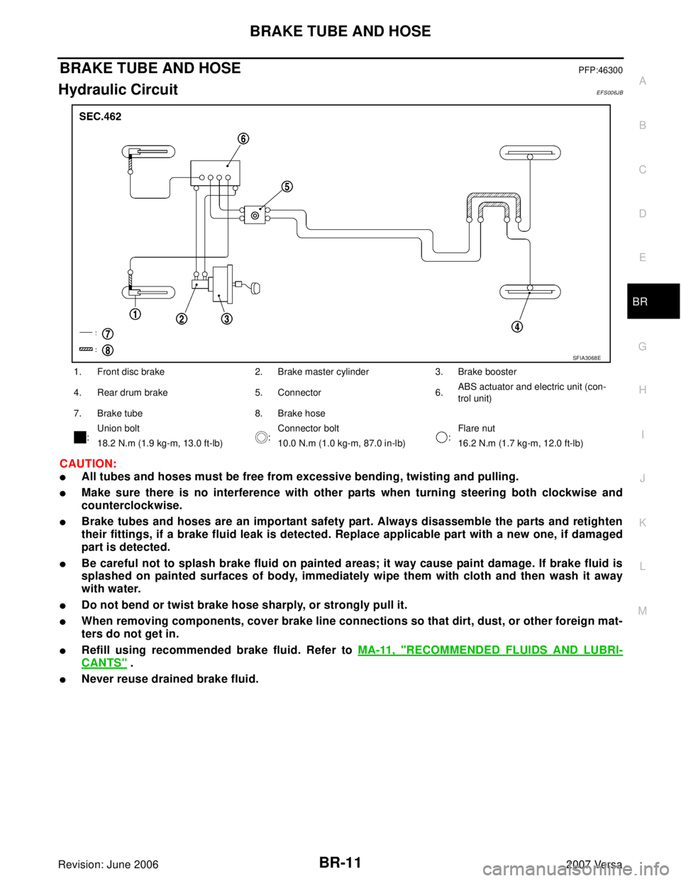
1. Front disc brake 2. Brake master cylinder 3. Brake booster
4. Rear drum brake 5. Connector 6.ABS actuator and electric unit (con-
trol unit)
7. Brake tube 8. Brake hose
:Union bolt
:Connector bolt
:Flare nut
18.2 N.m (1.9 kg-m, 13.0 ft-lb) 10.0 N.m (1.0 kg-m, 87.0 in-lb) 16.2 N.m (1.7 kg-m, 12.0 ft-lb)
SFIA3068E
Page 866 of 2896
CLUTCH MASTER CYLINDER
CL-9
D
E
F
G
H
I
J
K
L
MA
B
CL
Revision: June 20062007 Versa
CLUTCH MASTER CYLINDERPFP:30610
Removal and InstallationECS00FSZ
REMOVAL
1. Use one of the following methods to remove hose from master cylinder.
�Drain clutch fluid from reservoir tank and remove hose.
�Remove hose from master cylinder. Immediately plug hose and reservoir tank to prevent clutch fluid
from dripping.
CAUTION:
Keep painted surface of the body and other parts free of clutch fluid. If it spills, wipe up immedi-
ately and wash the affected area with water.
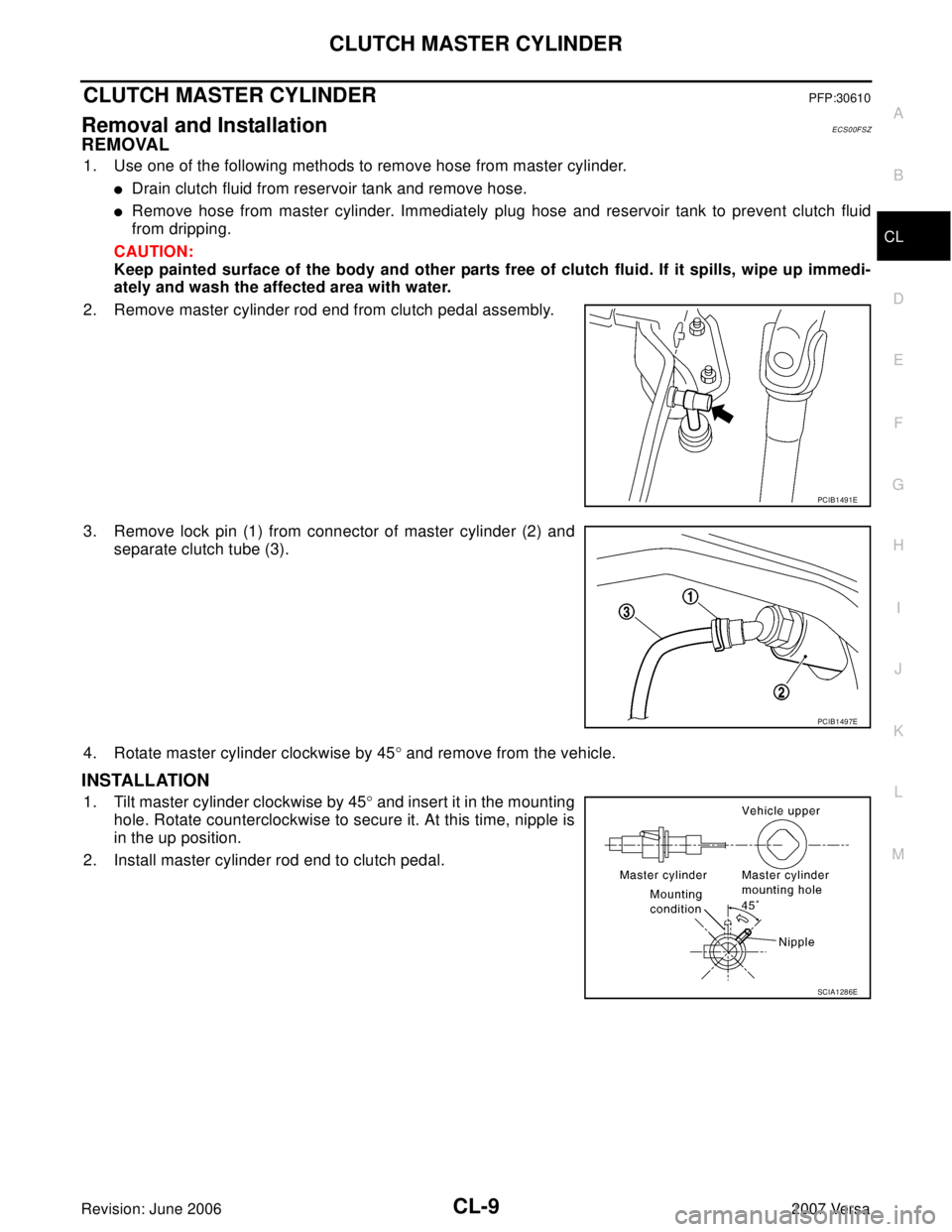
2. Remove master cylinder rod end from clutch pedal assembly.
3. Remove lock pin (1) from connector of master cylinder (2) and
separate clutch tube (3).
4. Rotate master cylinder clockwise by 45° and remove from the vehicle.
INSTALLATION
1. Tilt master cylinder clockwise by 45° and insert it in the mounting
hole. Rotate counterclockwise to secure it. At this time, nipple is
in the up position.
2. Install master cylinder rod end to clutch pedal.
PCIB1491E
PCIB1497E
SCIA1286E
Page 908 of 2896
PRECAUTIONS
CVT-11
D
E
F
G
H
I
J
K
L
MA
B
CVT
Revision: June 20062007 Versa
Calibration Data
PATTERN C
1. Replace the transaxle assembly first, and then replace TCM.
2. Perform the service of “PATTERN A”.
(Perform the service of “Pattern B” if TCM is replaced first.)
Removal and Installation Procedure for CVT Unit ConnectorUCS005XI
REMOVAL
Rotate bayonet ring counterclockwise, pull out CVT unit harness
connector upward and disconnect it.
SCIA7 411 E
SCIA2096E
Page 909 of 2896
CVT-12
PRECAUTIONS
Revision: June 20062007 Versa
INSTALLATION
1. Align CVT unit harness connector terminal body marking with
bayonet ring marking, insert CVT unit harness connector, and
then rotate bayonet ring clockwise.
2. Rotate bayonet ring clockwise until CVT unit harness connector
terminal body marking is aligned with the bayonet ring marking
(linear slit) as shown.
CAUTION:
�Securely align CVT unit harness connector terminal body
marking with bayonet ring marking (linear slit). Do not
make a half fit condition as shown.
�Do not mistake the bayonet ring marking (linear slit) for
other dent portion.
SCIA2097E
SCIA2098E
SCIA2099E
Page 1105 of 2896
CVT-208
TRANSAXLE ASSEMBLY
Revision: June 20062007 Versa
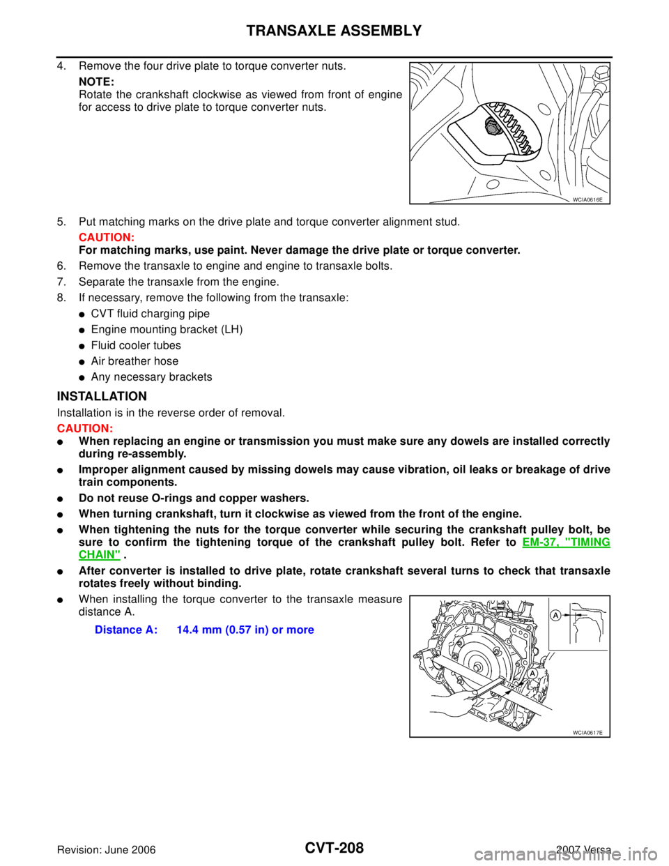
4. Remove the four drive plate to torque converter nuts.
NOTE:
Rotate the crankshaft clockwise as viewed from front of engine
for access to drive plate to torque converter nuts.
5. Put matching marks on the drive plate and torque converter alignment stud.
CAUTION:
For matching marks, use paint. Never damage the drive plate or torque converter.
6. Remove the transaxle to engine and engine to transaxle bolts.
7. Separate the transaxle from the engine.
8. If necessary, remove the following from the transaxle:
�CVT fluid charging pipe
�Engine mounting bracket (LH)
�Fluid cooler tubes
�Air breather hose
�Any necessary brackets
INSTALLATION
Installation is in the reverse order of removal.
CAUTION:
�When replacing an engine or transmission you must make sure any dowels are installed correctly
during re-assembly.
�Improper alignment caused by missing dowels may cause vibration, oil leaks or breakage of drive
train components.
�Do not reuse O-rings and copper washers.
�When turning crankshaft, turn it clockwise as viewed from the front of the engine.
�When tightening the nuts for the torque converter while securing the crankshaft pulley bolt, be
sure to confirm the tightening torque of the crankshaft pulley bolt. Refer to EM-37, "
TIMING
CHAIN" .
�After converter is installed to drive plate, rotate crankshaft several turns to check that transaxle
rotates freely without binding.
�When installing the torque converter to the transaxle measure
distance A.
WCIA0616E
Distance A: 14.4 mm (0.57 in) or more
WCIA0617E
Page 1204 of 2896
EVAPORATIVE EMISSION SYSTEM
EC-35
C
D
E
F
G
H
I
J
K
L
MA
EC
Revision: June 20062007 Versa
EVAP SERVICE PORT
Positive pressure is delivered to the EVAP system through the EVAP
service port. If fuel vapor leakage in the EVAP system occurs, use a
leak detector to locate the leak.
Removal and InstallationUBS00QBA
EVAP CANISTER
Tighten EVAP canister as shown in the figure.
EVAP CANISTER VENT CONTROL VALVE
1. Turn EVAP canister vent control valve counterclockwise.
�Lock (A)
�Unlock (B)
2. Remove the EVAP canister vent control valve.
Always replace O-ring with a new one.
How to Detect Fuel Vapor LeakageUBS00QBB
CAUTION:
�Never use compressed air or a high pressure pump.
�Do not exceed 4.12 kPa (0.042 kg/cm2 , 0.6 psi) of pressure in EVAP system.
NOTE:
�Do not start engine.
�Improper installation of EVAP service port adapter to the EVAP service port may cause a leak.
SEF 4 62 UC
PBIB1214E
PBIB3091E
Page 1231 of 2896
EC-62Revision: June 2006
ON BOARD DIAGNOSTIC (OBD) SYSTEM
2007 Versa
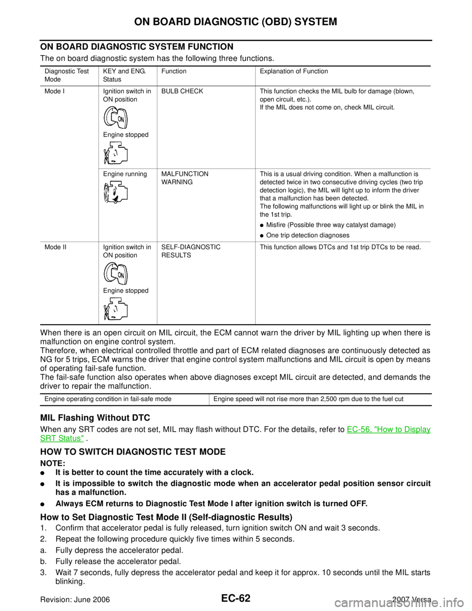
ON BOARD DIAGNOSTIC SYSTEM FUNCTION
The on board diagnostic system has the following three functions.
When there is an open circuit on MIL circuit, the ECM cannot warn the driver by MIL lighting up when there is
malfunction on engine control system.
Therefore, when electrical controlled throttle and part of ECM related diagnoses are continuously detected as
NG for 5 trips, ECM warns the driver that engine control system malfunctions and MIL circuit is open by means
of operating fail-safe function.
The fail-safe function also operates when above diagnoses except MIL circuit are detected, and demands the
driver to repair the malfunction.
MIL Flashing Without DTC
When any SRT codes are not set, MIL may flash without DTC. For the details, refer to EC-56, "How to Display
SRT Status" .
HOW TO SWITCH DIAGNOSTIC TEST MODE
NOTE:
�It is better to count the time accurately with a clock.
�It is impossible to switch the diagnostic mode when an accelerator pedal position sensor circuit
has a malfunction.
�Always ECM returns to Diagnostic Test Mode I after ignition switch is turned OFF.
How to Set Diagnostic Test Mode II (Self-diagnostic Results)
1. Confirm that accelerator pedal is fully released, turn ignition switch ON and wait 3 seconds.
2. Repeat the following procedure quickly five times within 5 seconds.
a. Fully depress the accelerator pedal.
b. Fully release the accelerator pedal.
3. Wait 7 seconds, fully depress the accelerator pedal and keep it for approx. 10 seconds until the MIL starts
blinking.
Diagnostic Test
ModeKEY and ENG.
Statu sFunction Explanation of Function
Mode I Ignition switch in
ON position
Engine stoppedBULB CHECK This function checks the MIL bulb for damage (blown,
open circuit, etc.).
If the MIL does not come on, check MIL circuit.
Engine running MALFUNCTION
WARNINGThis is a usual driving condition. When a malfunction is
detected twice in two consecutive driving cycles (two trip
detection logic), the MIL will light up to inform the driver
that a malfunction has been detected.
The following malfunctions will light up or blink the MIL in
the 1st trip.
�Misfire (Possible three way catalyst damage)
�One trip detection diagnoses
Mode II Ignition switch in
ON position
Engine stoppedSELF-DIAGNOSTIC
RESULTSThis function allows DTCs and 1st trip DTCs to be read.
Engine operating condition in fail-safe mode Engine speed will not rise more than 2,500 rpm due to the fuel cut