Page 714 of 2896

BL-225
C
D
E
F
G
H
J
K
L
MA
B
BL
Revision: June 20062007 Versa
Diagnostic Procedure 2EIS0093Z
Self-diagnostic results:
“CHAIN OF IMMU-KEY” displayed on CONSULT-II s")
NATS (NISSAN ANTI-THEFT SYSTEM)
BL-225
C
D
E
F
G
H
J
K
L
MA
B
BL
Revision: June 20062007 Versa
Diagnostic Procedure 2EIS0093Z
Self-diagnostic results:
“CHAIN OF IMMU-KEY” displayed on CONSULT-II screen
1. CONFIRM SELF-DIAGNOSTIC RESULTS
Confirm SELF-DIAGNOSTIC RESULTS “CHAIN OF IMMU-KEY”
displayed on CONSULT-II screen.
Is CONSULT-II screen displayed as shown in figure?
Yes >> GO TO 2.
No >> GO TO BL-222, "
SYMPTOM MATRIX CHART 1" .
2. CHECK NATS ANTENNA AMP. INSTALLATION
Check NATS antenna amp. installation. Refer to BL-230, "
How to Replace NATS Antenna Amp." .
OK or NG
OK >> GO TO 3.
NG >> Reinstall NATS antenna amp. correctly.
3. CHECK NATS IGNITION KEY ID CHIP
Start engine with another registered NATS ignition key.
Does the engine start?
Yes >> Ignition key ID chip is malfunctioning.
�Replace the ignition key
�Perform initialization with CONSULT-II
For initialization, refer to “CONSULT-II Operation Manual NATS”
No >> GO TO 4.
4. CHECK POWER SUPPLY FOR NATS ANTENNA AMP.
1. Turn ignition switch “OFF”.
2. Check voltage between NATS antenna amp. connector and ground.
OK or NG
OK >> GO TO 5.
NG >> Check the following.
�20A fuse [No. 53, located in IPDM E/R]
�Harness for open or short between fuse and NATS
antenna amp.
PIIA1263E
NATS antenna amp.
connectorTerminal
Voltage [V]
(Approx.)
(+) (–)
M21 1 Ground Battery voltage
PIIB6589E
Page 716 of 2896

BL-227
C
D
E
F
G
H
J
K
L
MA
B
BL
Revision: June 20062007 Versa
Diagnostic Procedure 3EIS00940
Self-diagnostic results:
“ID DISCORD, IMM-ECM” displayed on CONSULT-II")
NATS (NISSAN ANTI-THEFT SYSTEM)
BL-227
C
D
E
F
G
H
J
K
L
MA
B
BL
Revision: June 20062007 Versa
Diagnostic Procedure 3EIS00940
Self-diagnostic results:
“ID DISCORD, IMM-ECM” displayed on CONSULT-II screen
1. CONFIRM SELF-DIAGNOSTIC RESULTS
Confirm SELF-DIAGNOSTIC RESULTS “ID DISCORD, IMM-ECM” displayed on CONSULT-II screen.
NOTE:
“ID DISCORD IMM-ECM”:
Registered ID of BCM is in discord with that of ECM.
Is CONSULT-II screen displayed as shown in figure?
Yes >> GO TO 2.
No >> GO TO BL-222, "
SYMPTOM MATRIX CHART 1" .
2. PERFORM INITIALIZATION WITH CONSULT-II
Perform initialization with CONSULT-II. Re-register all NATS ignition key IDs.
For initialization, refer to “CONSULT-II Operation Manual NATS”.
NOTE:
If the initialization is not completed or malfunctions, CONSULT-II
shows message on the screen.
Can the system be initialized?
Ye s > >�Start engine. (END)
�(System initialization had not been completed.)
No >> ECM is malfunctioning.
�Replace ECM.
�Perform initialization with CONSULT-II
For initialization, refer to “CONSULT-II Operation
Manual NATS”
PIIA1262E
SEL297W
Page 717 of 2896

Revision: June 20062007 Versa
Diagnostic Procedure 4EIS00941
“COMBINATION METER (SECURITY) DOES NOT LIGHT UP”
1. CHECK FUSE
Check 10A fuse [No.13, located in")
BL-228
NATS (NISSAN ANTI-THEFT SYSTEM)
Revision: June 20062007 Versa
Diagnostic Procedure 4EIS00941
“COMBINATION METER (SECURITY) DOES NOT LIGHT UP”
1. CHECK FUSE
Check 10A fuse [No.13, located in the fuse block (J/B)]
OK or NG
OK >> GO TO 2.
NG >> Replace fuse.
2. CHECK COMBINATION METER (SECURITY)
1. Install 10A fuse.
2. Start engine and turn ignition switch OFF.
3. Check if the combination meter (security) lights up.
OK or NG
OK >> INSPECTION END.
NG >> GO TO 3.
3. CHECK COMBINATION METER (SECURITY) POWER SUPPLY CIRCUIT
1. Disconnect combination meter (security) connector.
2. Check voltage between combination meter (security) connector and ground.
OK or NG
OK >> GO TO 4.
NG >> Check harness for open or short between fuse and com-
bination meter (security).
4. CHECK BCM FUNCTION
1. Connect combination meter (security) connector.
2. Disconnect BCM connector.
3. Check voltage between BCM connector and ground.
OK or NG
OK >> BCM is malfunctioning.
�Replace BCM. Refer to BCS-25, "Removal and Instal-
lation of BCM" .
�Perform initialization with CONSULT-II
�For initialization, refer to “CONSULT-II Operation
Manual NATS”
NG >> Check the following.
�Harness for open or short between combination meter (security) and BCM
�Indicator lamp condition Combination meter (security) should light up.
Combination meter
(security) connec-
torTe r m i n a l
Voltage [V]
(Approx.)
(+) (-)
M24 27 Ground Battery voltage
PIIB6593E
BCM connectorTe r m i n a l
Voltage [V]
(Approx.)
(+) (-)
M18 23 Ground Battery voltage
PIIB6594E
Page 718 of 2896

BL-229
C
D
E
F
G
H
J
K
L
MA
B
BL
Revision: June 20062007 Versa
Diagnostic Procedure 5EIS00942
Self-diagnostic results:
“LOCK MODE” displayed on CONSULT-II screen
1.")
NATS (NISSAN ANTI-THEFT SYSTEM)
BL-229
C
D
E
F
G
H
J
K
L
MA
B
BL
Revision: June 20062007 Versa
Diagnostic Procedure 5EIS00942
Self-diagnostic results:
“LOCK MODE” displayed on CONSULT-II screen
1. CONFIRM SELF-DIAGNOSTIC RESULTS
Confirm SELF-DIAGNOSTIC RESULTS “LOCK MODE” is displayed
on CONSULT-II screen.
Is CONSULT-II screen displayed as shown in figure?
Yes >> GO TO 2.
No >> GO TO BL-222, "
SYMPTOM MATRIX CHART 1" .
2. ESCAPE FROM LOCK MODE
1. Turn ignition switch OFF.
2. Turn ignition switch ON with registered key. (Do not start engine.) Wait 5 seconds.
3. Return the key to OFF position. Wait 5 seconds.
4. Repeat steps 2 and 3 twice (total of three cycles).
5. Start the engine.
Does engine start?
Yes >> System is OK (Now system is escaped from “LOCK MODE”).
No >> GO TO 3.
3. PERFORM INITIALIZATION WITH CONSULT-II
Perform initialization with CONSULT-II.
For initialization, refer to “CONSULT-II Operation Manual NATS”.
NOTE:
If the initialization is not completed or malfunctions, CONSULT-II
shows the message on the screen.
Can the system be initialized?
Yes >> System is OK.
No >> GO TO 4.
PIIA1264E
SEL297W
Page 722 of 2896

5. Lower")
BODY REPAIR
BL-233
C
D
E
F
G
H
J
K
L
MA
B
BL
Revision: June 20062007 Versa
1. Upper dash assembly
2. Lower dash assembly
3. Lower dash crossmember
4. Front pillar inner reinforcement (RH&LH)
5. Lower dash reinforcement
6. 4th crossmember (RH&LH)
7. Front side member rear extension (RH&LH)
8. 3rd crossmember (RH&LH)
9. Front seat outer rear bracket (RH&LH)
10. Front seat inner rear bracket (RH&LH)
11. 2nd crossmember (RH&LH)
12. Front seat outer front bracket (RH&LH)
13. Front seat inner front bracket (RH&LH)
14. Fender bracket (RH&LH)
15. Strut housing assembly RH
16. Cowl top side upper (RH&LH)
17. Front strut housing (RH&LH)
18. Upper torque rod reinforcement
19. Closing plate assembly RH
20. Engine mount reinforcement
21. Strut tower front reinforcement RH
22. Front hoodledge lower RH
23. Frame bracket outer (RH&LH)
24. Front bumper support bracket (RH&LH)
25. Closing plate (RH&LH)
26. Front suspension rear bracket (RH&LH)
27. Front side member outrigger (RH&LH)
28. Front side member assembly (RH&LH)
29. Front side member (RH&LH)
30. Frame bracket (RH&LH)
31. Closing plate assembly LH
32. Hoodledge connector (RH&LH)
33. Radiator core side support (RH&LH)
34. Radiator core support upper (RH&LH)
35. Hoodledge upper (RH&LH)
36. Hoodledge reinforcement assembly (RH&LH)
37. Dash side (RH&LH)
38. Dash side assembly (RH& LH)
39. Front floor reinforcement (RH&LH)
40. Front floor front (RH&LH)
41. Front floor center
42. Rear seat crossmember
43. Rear center crossmember
44. Rear seat upper crossmember
45. Rear side member (RH&LH)
46. Sill inner extension (RH&LH)
47. Rear side member extension (RH&LH)
48. Rear side member assembly (RH & LH)
49. Rear floor front
Page 736 of 2896
BODY REPAIR
BL-247
C
D
E
F
G
H
J
K
L
MA
B
BL
Revision: June 20062007 Versa
ENGINE COMPARTMENT
Measurement
LIIA2610E
Page 789 of 2896
BR-6
BRAKE PEDAL
Revision: June 20062007 Versa
BRAKE PEDALPFP:46501
Inspection and AdjustmentEFS006J6
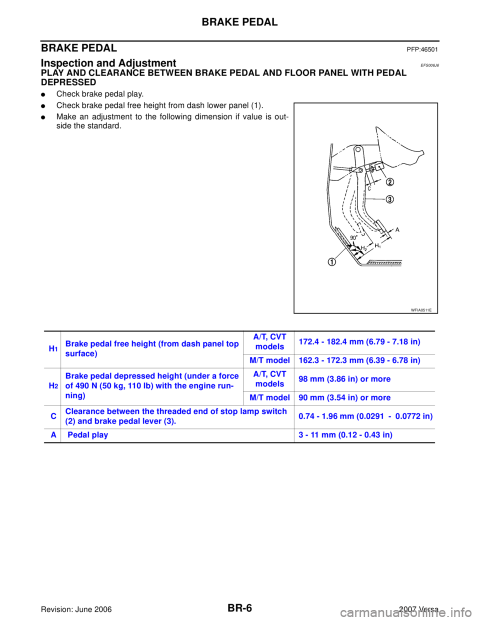
PLAY AND CLEARANCE BETWEEN BRAKE PEDAL AND FLOOR PANEL WITH PEDAL
DEPRESSED
�Check brake pedal play.
�Check brake pedal free height from dash lower panel (1).
�Make an adjustment to the following dimension if value is out-
side the standard.
WFIA0511E
H1Brake pedal free height (from dash panel top
surface)A/T, CVT
models172.4 - 182.4 mm (6.79 - 7.18 in)
M/T model 162.3 - 172.3 mm (6.39 - 6.78 in)
H
2
Brake pedal depressed height (under a force
of 490 N (50 kg, 110 lb) with the engine run-
ning)A/T, CVT
models98 mm (3.86 in) or more
M/T model 90 mm (3.54 in) or more
CClearance between the threaded end of stop lamp switch
(2) and brake pedal lever (3).0.74 - 1.96 mm (0.0291 - 0.0772 in)
A Pedal play 3 - 11 mm (0.12 - 0.43 in)
Page 790 of 2896

BRAKE PEDAL
BR-7
C
D
E
G
H
I
J
K
L
MA
B
BR
Revision: June 20062007 Versa
ADJUSTMENT
1. Loosen stop lamp switch by rotating it counterclockwise by 45°.
2. Loosen lock nut on input rod, then rotate input rod to set pedal to
the specified height, and tighten lock nut.
CAUTION:
Make sure that the threaded end of input rod stays inside
clevis.
3. With the pedal pulled and held by hand, press stop lamp switch
until its threaded end contacts brake pedal lever.
4. With the threaded end of stop lamp switch contacting brake
pedal lever, rotate the switch clockwise by 45° to secure.
CAUTION:
Make sure that the clearance (C) is within the standard.
Refer to BR-6, "
Inspection and Adjustment" .
5. Check the pedal play.
CAUTION:
Make sure that stop lamps go off when brake pedal is
released.
6. Start engine to check brake pedal depressed height. Refer to
BR-6, "
Inspection and Adjustment" .
Removal and InstallationEFS006J7
COMPONENTS
Lock nut : Refer to BR-20, "COMPONENTS" .
SFIA3064E
1. Snap pin 2. Stop lamp switch 3. Clip
4. Brake pedal assembly 5. Clevis 6. Brake pedal pad
SFIA3065E