Page 4 of 54

WW-4
FRONT WIPER AND WASHER SYSTEM
Revision: 2006 November2007 350Z
FRONT WIPER AND WASHER SYSTEMPFP:28810
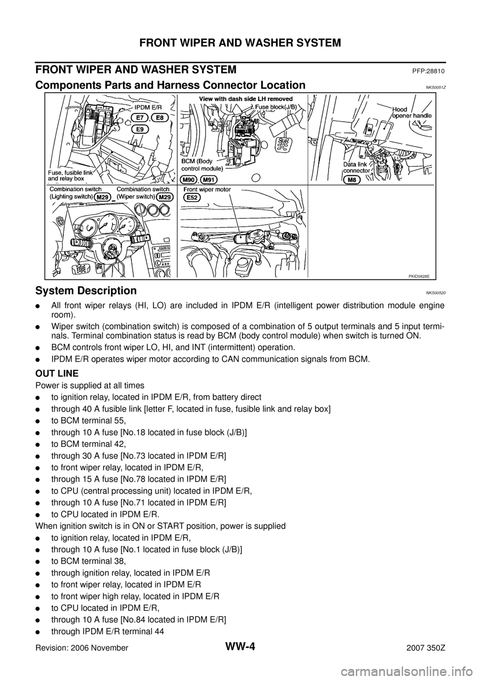
Components Parts and Harness Connector LocationNKS0051Z
System DescriptionNKS00520
�All front wiper relays (HI, LO) are included in IPDM E/R (intelligent power distribution module engine
room).
�Wiper switch (combination switch) is composed of a combination of 5 output terminals and 5 input termi-
nals. Terminal combination status is read by BCM (body control module) when switch is turned ON.
�BCM controls front wiper LO, HI, and INT (intermittent) operation.
�IPDM E/R operates wiper motor according to CAN communication signals from BCM.
OUT LINE
Power is supplied at all times
�to ignition relay, located in IPDM E/R, from battery direct
�through 40 A fusible link [letter F, located in fuse, fusible link and relay box]
�to BCM terminal 55,
�through 10 A fuse [No.18 located in fuse block (J/B)]
�to BCM terminal 42,
�through 30 A fuse [No.73 located in IPDM E/R]
�to front wiper relay, located in IPDM E/R,
�through 15 A fuse [No.78 located in IPDM E/R]
�to CPU (central processing unit) located in IPDM E/R,
�through 10 A fuse [No.71 located in IPDM E/R]
�to CPU located in IPDM E/R.
When ignition switch is in ON or START position, power is supplied
�to ignition relay, located in IPDM E/R,
�through 10 A fuse [No.1 located in fuse block (J/B)]
�to BCM terminal 38,
�through ignition relay, located in IPDM E/R
�to front wiper relay, located in IPDM E/R
�to front wiper high relay, located in IPDM E/R
�to CPU located in IPDM E/R,
�through 10 A fuse [No.84 located in IPDM E/R]
�through IPDM E/R terminal 44
PKID0828E
Page 18 of 54

WW-18
FRONT WIPER AND WASHER SYSTEM
Revision: 2006 November2007 350Z
6. INSPECTION END
Preliminary CheckNKS00528
CHECK POWER SUPPLY AND GROUND CIRCUIT
1. CHECK FUSES AND FUSIBLE LINK
Check for blown fuses and fusible link.
Refer to WW-11, "
Wiring Diagram — WIPER —" .
OK or NG
OK >> GO TO 2
NG >> If fuse is blown, be sure to eliminate the cause of malfunction before installing new fuse, Refer to
PG-4, "
POWER SUPPLY ROUTING CIRCUIT" .
2. CHECK POWER SUPPLY CIRCUIT
1. Turn ignition switch OFF.
2. Disconnect BCM connector.
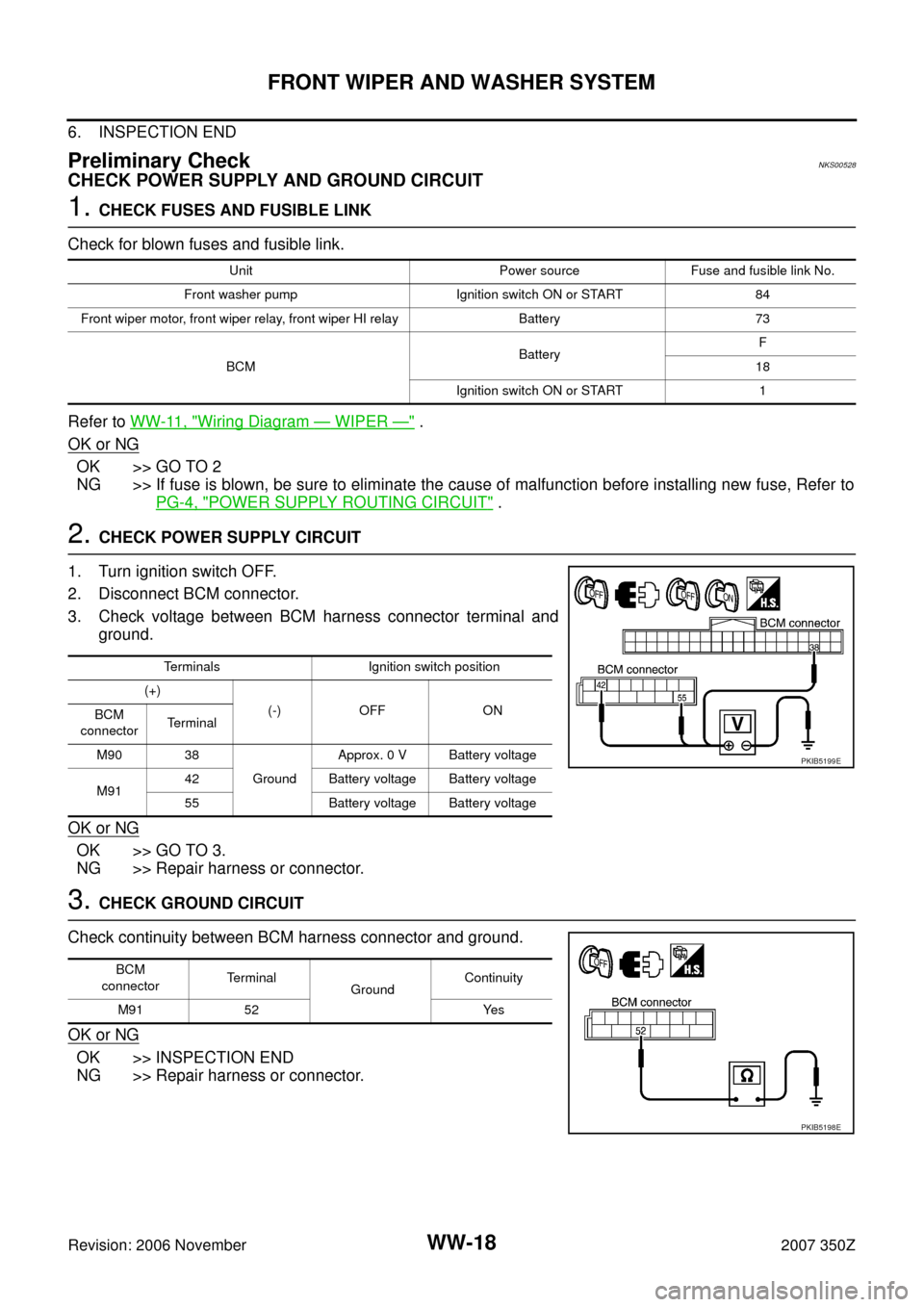
3. Check voltage between BCM harness connector terminal and
ground.
OK or NG
OK >> GO TO 3.
NG >> Repair harness or connector.
3. CHECK GROUND CIRCUIT
Check continuity between BCM harness connector and ground.
OK or NG
OK >> INSPECTION END
NG >> Repair harness or connector.
Unit Power source Fuse and fusible link No.
Front washer pump Ignition switch ON or START 84
Front wiper motor, front wiper relay, front wiper HI relay Battery 73
BCMBatteryF
18
Ignition switch ON or START 1
Terminals Ignition switch position
(+)
(-) OFF ON
BCM
connectorTerminal
M90 38
GroundApprox. 0 V Battery voltage
M9142 Battery voltage Battery voltage
55 Battery voltage Battery voltage
PKIB5199E
BCM
connectorTe r m i n a l
GroundContinuity
M91 52 Yes
PKIB5198E
Page 36 of 54

WW-36
REAR WIPER AND WASHER SYSTEM
Revision: 2006 November2007 350Z
REAR WIPER AND WASHER SYSTEMPFP:28710
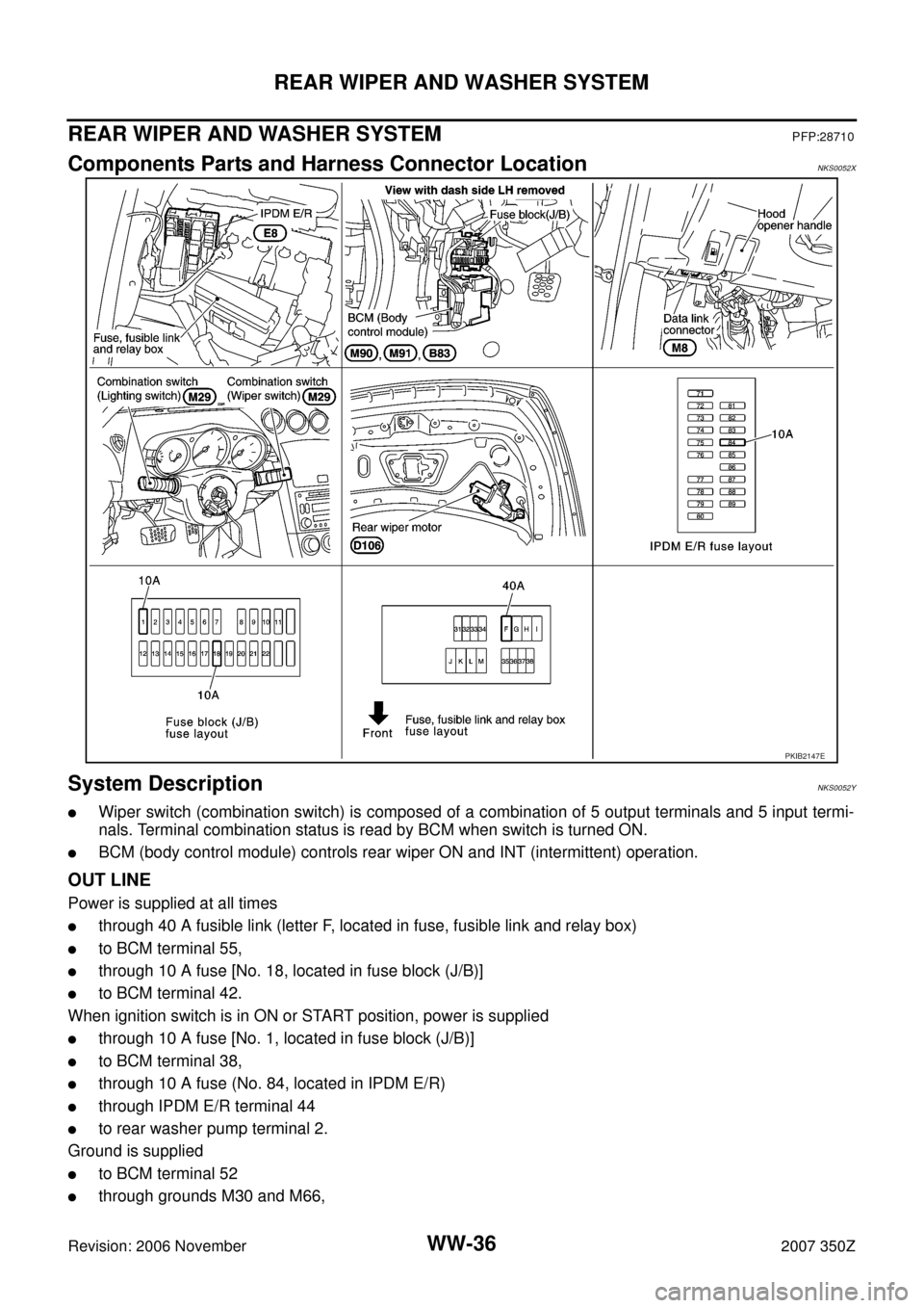
Components Parts and Harness Connector LocationNKS0052X
System DescriptionNKS0052Y
�Wiper switch (combination switch) is composed of a combination of 5 output terminals and 5 input termi-
nals. Terminal combination status is read by BCM when switch is turned ON.
�BCM (body control module) controls rear wiper ON and INT (intermittent) operation.
OUT LINE
Power is supplied at all times
�through 40 A fusible link (letter F, located in fuse, fusible link and relay box)
�to BCM terminal 55,
�through 10 A fuse [No. 18, located in fuse block (J/B)]
�to BCM terminal 42.
When ignition switch is in ON or START position, power is supplied
�through 10 A fuse [No. 1, located in fuse block (J/B)]
�to BCM terminal 38,
�through 10 A fuse (No. 84, located in IPDM E/R)
�through IPDM E/R terminal 44
�to rear washer pump terminal 2.
Ground is supplied
�to BCM terminal 52
�through grounds M30 and M66,
PKIB2147E
Page 42 of 54

WW-42
REAR WIPER AND WASHER SYSTEM
Revision: 2006 November2007 350Z
Preliminary CheckNKS00532
CHECK POWER SUPPLY AND GROUND CIRCUIT
1. CHECK FUSES AND FUSIBLE LINK
Check for blown fuses and fusible link.
Refer to WW-38, "
Wiring Diagram — WIP/ R —" .
OK or NG
OK >> GO TO 2.
NG >> If fuse is blown, be sure to eliminate cause of malfunction before installing new fuse. Refer to PG-
4, "POWER SUPPLY ROUTING CIRCUIT" .
2. CHECK POWER SUPPLY CIRCUIT
1. Turn ignition switch OFF.
2. Disconnect BCM connector.
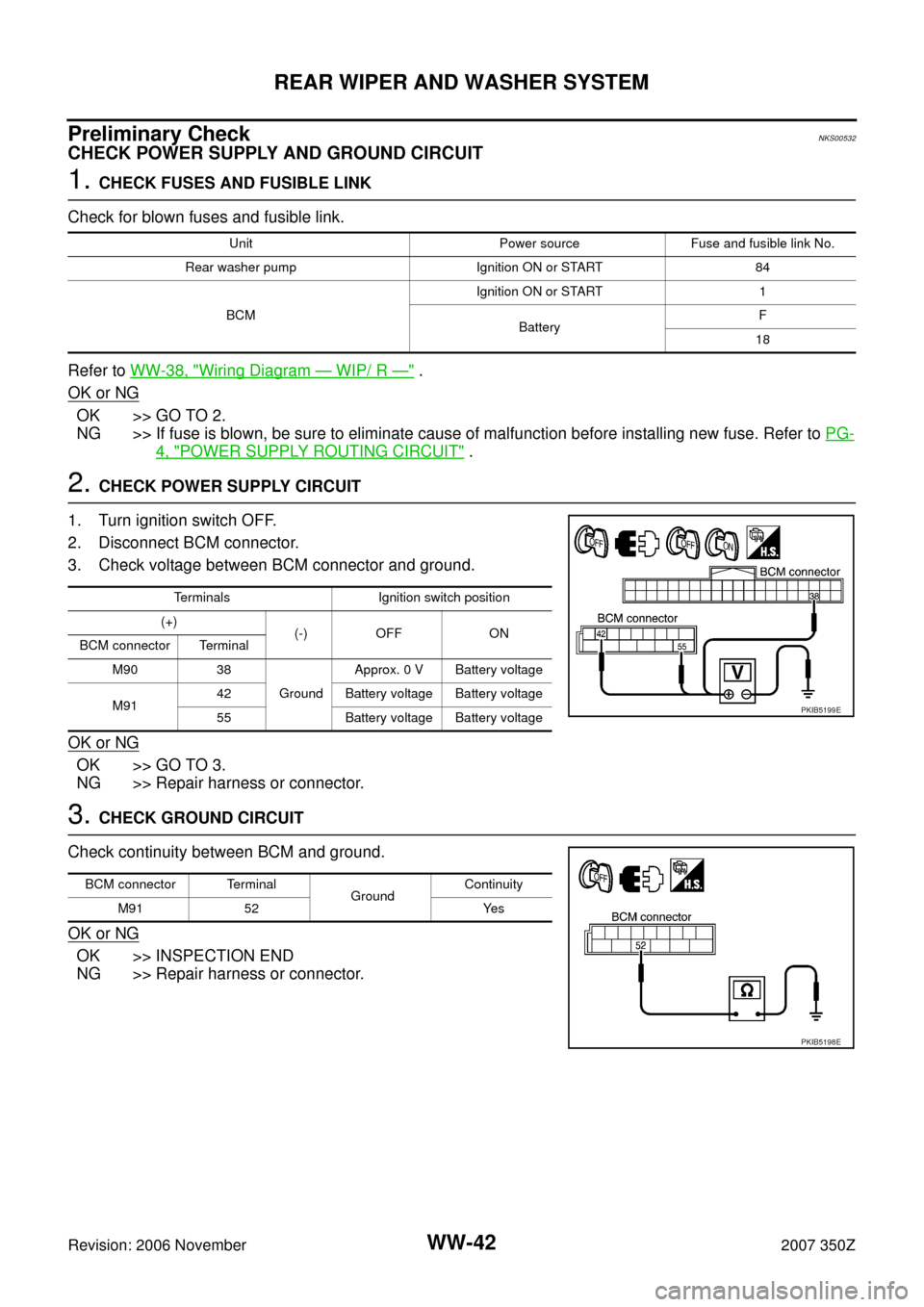
3. Check voltage between BCM connector and ground.
OK or NG
OK >> GO TO 3.
NG >> Repair harness or connector.
3. CHECK GROUND CIRCUIT
Check continuity between BCM and ground.
OK or NG
OK >> INSPECTION END
NG >> Repair harness or connector.
Unit Power source Fuse and fusible link No.
Rear washer pump Ignition ON or START 84
BCMIgnition ON or START 1
BatteryF
18
Terminals Ignition switch position
(+)
(-) OFF ON
BCM connector Terminal
M90 38
GroundApprox. 0 V Battery voltage
M9142 Battery voltage Battery voltage
55 Battery voltage Battery voltage
PKIB5199E
BCM connector Terminal
GroundContinuity
M91 52 Yes
PKIB5198E