Page 8 of 130

RF-8
SQUEAK AND RATTLE TROUBLE DIAGNOSES
Revision: 2006 November2007 350Z
TRUNK
Trunk noises are often caused by a loose jack or loose items put into the trunk by the owner.
In addition look for:
1. Trunk lid dumpers out of adjustment
2. Trunk lid striker out of adjustment
3. The trunk lid torsion bars knocking together
4. A loose license plate or bracket
Most of these incidents can be repaired by adjusting, securing or insulating the item(s) or component(s) caus-
ing the noise.
SUNROOF/HEADLINING
Noises in the sunroof/headlining area can often be traced to one of the following:
1. Sunroof lid, rail, linkage or seals making a rattle or light knocking noise
2. Sunvisor shaft shaking in the holder
3. Front or rear windshield touching headlining and squeaking
Again, pressing on the components to stop the noise while duplicating the conditions can isolate most of these
incidents. Repairs usually consist of insulating with felt cloth tape.
SEATS
When isolating seat noise it's important to note the position the seat is in and the load placed on the seat when
the noise is present. These conditions should be duplicated when verifying and isolating the cause of the
noise.
Cause of seat noise include:
1. Headrest rods and holder
2. A squeak between the seat pad cushion and frame
3. The rear seatback lock and bracket
These noises can be isolated by moving or pressing on the suspected components while duplicating the con-
ditions under which the noise occurs. Most of these incidents can be repaired by repositioning the component
or applying urethane tape to the contact area.
UNDERHOOD
Some interior noise may be caused by components under the hood or on the engine wall. The noise is then
transmitted into the passenger compartment.
Causes of transmitted underhood noise include:
1. Any component mounted to the engine wall
2. Components that pass through the engine wall
3. Engine wall mounts and connectors
4. Loose radiator mounting pins
5. Hood bumpers out of adjustment
6. Hood striker out of adjustment
These noises can be difficult to isolate since they cannot be reached from the interior of the vehicle. The best
method is to secure, move or insulate one component at a time and test drive the vehicle. Also, engine RPM
or load can be changed to isolate the noise. Repairs can usually be made by moving, adjusting, securing, or
insulating the component causing the noise.
Page 88 of 130

RF-88
SOFT TOP
Revision: 2006 November2007 350Z
Removal and Installation of Soft Top AssemblyNIS0007R
CAUTION:
Install fender cover to protect rear fender.
REMOVAL
1. Fully open storage lid with soft top retracting.
2. Remove seat belt sholder bolt. Refer to SB-6, "
REMOVAL OF SEAT BELT RETRACTOR" .
3. Remove rear side finisher. Refer to EI-37, "
REAR SIDE FINISHER" .
4. Remove back panel finisher. Refer to EI-42, "
BACK PANEL FINISHER" .
5. Loosen bolts at soft top mounting bracket (front).
CAUTION:
Do not remove soft top mounting bracket (front) (body
side).
6. Close soft top until 5th bow are raised and folded with C-link.
Loosen nut at soft top mounting bracket (rear). Then fold (open)
soft top assembly completely.
CAUTION:
Do not remove soft top mounting bracket (rear) (body side).
7. Remove back panel bracket.
1. Front lock 2. Front lock finisher 3. TORX bolt (T30)
4. Welt 5. Front center retainer 6. Clip
7. Screw 8. Front lock striker, RH 9. Front lock striker, center
10. Front lock striker, LH 11. Bolt 12. B link retainer
13. A link retainer 14. A link weather strip 15. B link weather-strip
16. C link and 5th bow weather strip 17. Soft top switch bracket 1 18. Soft top switch bracket 2
19. C link retainer 20. Plate rail RR bracket 21. 5th bow operating strut rod
22. Nut 23. Holder 24. Soft top frame
25. Soft top cover 26. 5th bow retainer 27. 1st bow
28. 2nd bow 29. 3rd bow 30. 4th bow
31. 5th bow 32. A link 33. B link
34. C link
Nut: 28.0 N·m (2.9 kg-m, 21 ft-lb)
PIIA7824E
Bolt: 28.0 N·m (2.9 kg-m, 21 ft-lb)
PIIA7877E
Page 89 of 130

SOFT TOP
RF-89
C
D
E
F
G
H
J
K
L
MA
B
RF
Revision: 2006 November2007 350Z
8. Remove bolts, at the soft top mounting plate and shims.
CAUTION:
Do not replace left and right shims with each one with dif-
ferent thickness.
9. Disconnect harness connector.
10. Lift up soft top assembly from left and right, and then remove soft top assembly.
CAUTION:
2 workers are required for the heavy load of approximately 40 kg (89 lb).
INSTALLATION
Install in the reverse order of removal except the order of tightening bolts and nuts. (See note below.)
NOTE:
Before tighten soft top fixing bolts and nuts, make sure that soft top is sat on each pins from soft top mounting
brackets without any gaps.
To sit soft top correctly, follow this order.
1. Push soft top assembly down when nuts at soft top mounting bracket (rear) is tighten.
2. Close soft top until the angle of A-link becomes vertical against ground, then tighten bolts at soft top
mounting bracket (front).
3. Tighten bolts at soft top mounting plate with shims, then attach back panel bracket with bolts. Bolt: 28.0 N·m (2.9 kg-m, 21 ft-lb)
PIIA7863E
PIIA7878E
PIIB1302E
Page 96 of 130
RF-96
SOFT TOP
Revision: 2006 November2007 350Z
29. Open harness connector cover, and then disconnect defogger
harness connector from terminal.
30. Open soft top about 90 degrees.
31. Remove soft top wire from A link.
32. Remove soft top cover wire rear bracket from C link.
33. Remove spring from C link.
34. Pull out soft top cover frontward from 1st bow.
PIIB1304E
PIIB1288E
PIIB0989E
PIIB0985E
PIIB1305E
Page 101 of 130
SOFT TOP
RF-101
C
D
E
F
G
H
J
K
L
MA
B
RF
Revision: 2006 November2007 350Z
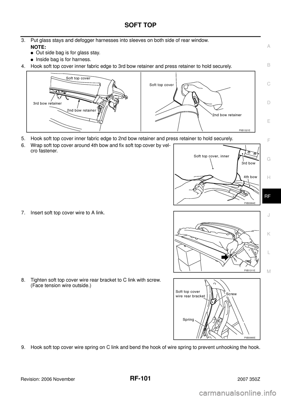
3. Put glass stays and defogger harnesses into sleeves on both side of rear window.
NOTE:
�Out side bag is for glass stay.
�Inside bag is for harness.
4. Hook soft top cover inner fabric edge to 3rd bow retainer and press retainer to hold securely.
5. Hook soft top cover inner fabric edge to 2nd bow retainer and press retainer to hold securely.
6. Wrap soft top cover around 4th bow and fix soft top cover by vel-
cro fastener.
7. Insert soft top cover wire to A link.
8. Tighten soft top cover wire rear bracket to C link with screw.
(Face tension wire outside.)
9. Hook soft top cover wire spring on C link and bend the hook of wire spring to prevent unhooking the hook.
PIIB1321E
PIIB0984E
PIIB1311E
PIIB0985E
Page 102 of 130
RF-102
SOFT TOP
Revision: 2006 November2007 350Z
10. Put soft top cover on 1st bow.
11. Align soft top cover hole and grommet hole at the 1st bow.
12. Tighten screws on 1st bow with front center retainer.
13. Apply EPT seal to A link installation position.
CAUTION:
Install EPT seal to the original position.
14. Put soft top cover on C link lower.
NOTE:
�Make sure that vinyl tube is on C link bottom end bracket.
�Be careful not to pull soft top cover with too much tension.
PIIB0988E
PIIB0994E
PIIB1441E
PIIB1320E
Page 107 of 130
SOFT TOP
RF-107
C
D
E
F
G
H
J
K
L
MA
B
RF
Revision: 2006 November2007 350Z
Removal and Installation of SwitchesNIS0007T
REMOVAL
1. Uninstall soft top assembly from the vehicle. Remove roof actuator (RH/LH) from the soft top.
2. Remove harness tie wrap band at the left side of the soft top.
3. Remove limit switches with plate rail RR bracket by removing
bolt.
4. Remove limit switches with soft top switch bracket1 by removing
bolt.
5. Remove limit switches with soft top switch bracket 2 by remov-
ing bolt.
INSTALLATION
Install in the reverse order of removal.
NOTE:
Wire harnesses correctly to avoid following situation.
�Pinching harnesses by frame.
�Tangling harnesses by frame and links.
�Pulling harnesses between fixing point by harness clips.
PIIA9750E
PIIA9752E
PIIA9751E
Page 123 of 130
STORAGE LID
RF-123
C
D
E
F
G
H
J
K
L
MA
B
RF
Revision: 2006 November2007 350Z
STORAGE LIDPFP:97002
Removal and Installation of Storage Lid AssemblyNIS0007Z
REMOVAL
1. Disconnect storage lid actuator connector.
2. Remove bolts, and then remove storage lid striker.
NOTE:
�2 or more workers are required.
�Paint matching marks to check location for installation.
3. Remove nuts which is connecting the storage lid upper bracket
and the storage lid lower bracket.
NOTE:
Paint matching marks to check location for installation.
4. Remove nuts of storage lid hinge, and then remove storage lid,
spacers and shims.
INSTALLATION
1. Install in the reverse order of removal.
2. Install storage lid, and then adjust fitting of lid.
1. Storage lid 2. Storage outer protector 3. Spacer
4. Shim 5. Storage lid hinge 6. Storage lid striker
7. Storage lid upper bracket 8. Storage lid lower bracket 9. 5th bow lock
10. 5th bow unlock actuator 11. 5th bow closure motor
PIIA8284E
PIIA7953E