Page 83 of 130

SOFT TOP
RF-83
C
D
E
F
G
H
J
K
L
MA
B
RF
Revision: 2006 November2007 350Z
Check Passenger Side Seat Operate Signal 2NIS0007K
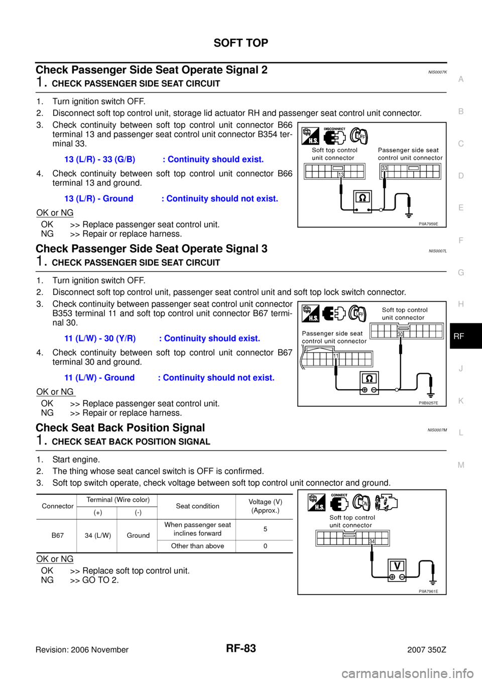
1. CHECK PASSENGER SIDE SEAT CIRCUIT
1. Turn ignition switch OFF.
2. Disconnect soft top control unit, storage lid actuator RH and passenger seat control unit connector.
3. Check continuity between soft top control unit connector B66
terminal 13 and passenger seat control unit connector B354 ter-
minal 33.
4. Check continuity between soft top control unit connector B66
terminal 13 and ground.
OK or NG
OK >> Replace passenger seat control unit.
NG >> Repair or replace harness.
Check Passenger Side Seat Operate Signal 3NIS0007L
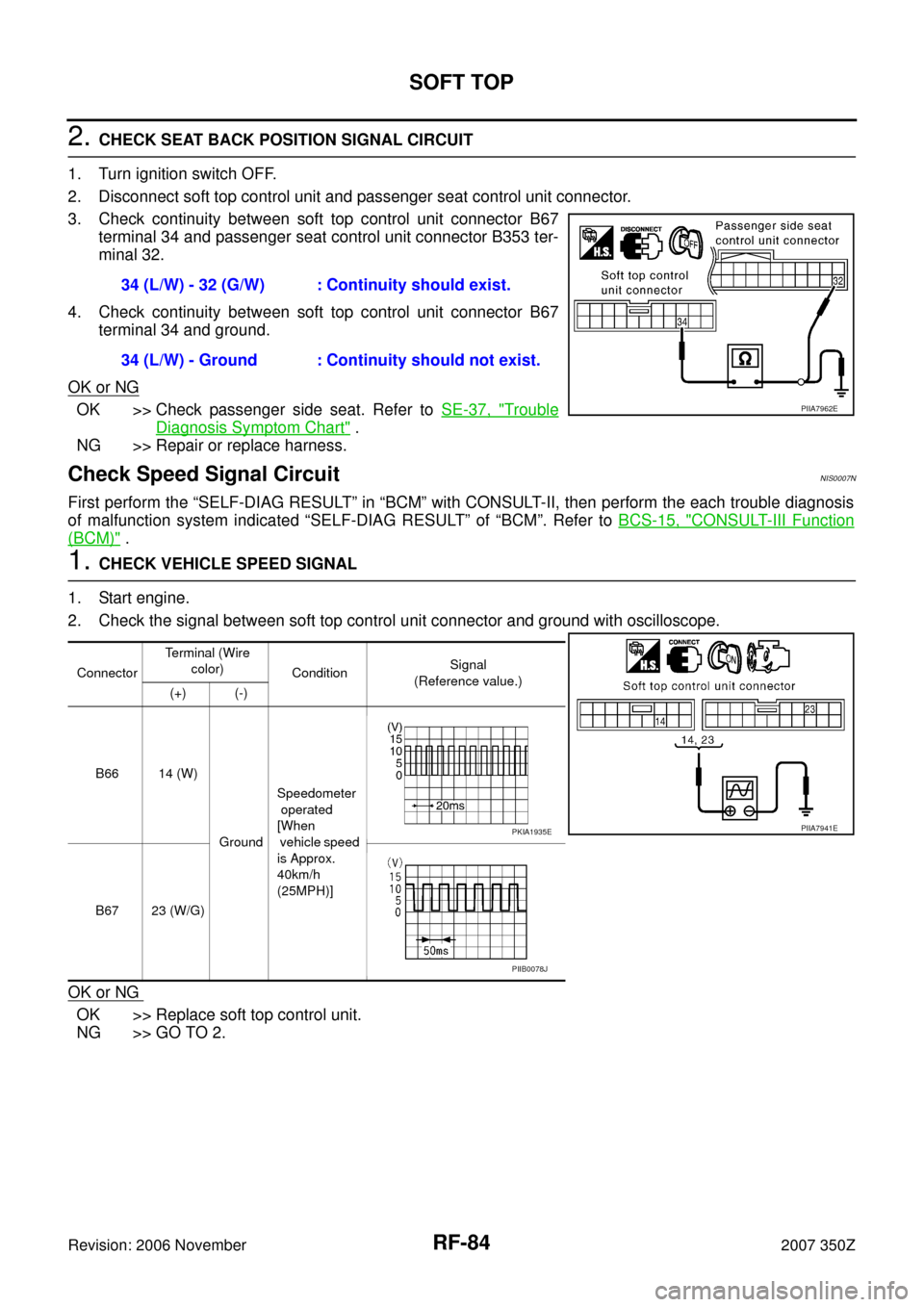
1. CHECK PASSENGER SIDE SEAT CIRCUIT
1. Turn ignition switch OFF.
2. Disconnect soft top control unit, passenger seat control unit and soft top lock switch connector.
3. Check continuity between passenger seat control unit connector
B353 terminal 11 and soft top control unit connector B67 termi-
nal 30.
4. Check continuity between soft top control unit connector B67
terminal 30 and ground.
OK or NG
OK >> Replace passenger seat control unit.
NG >> Repair or replace harness.
Check Seat Back Position SignalNIS0007M
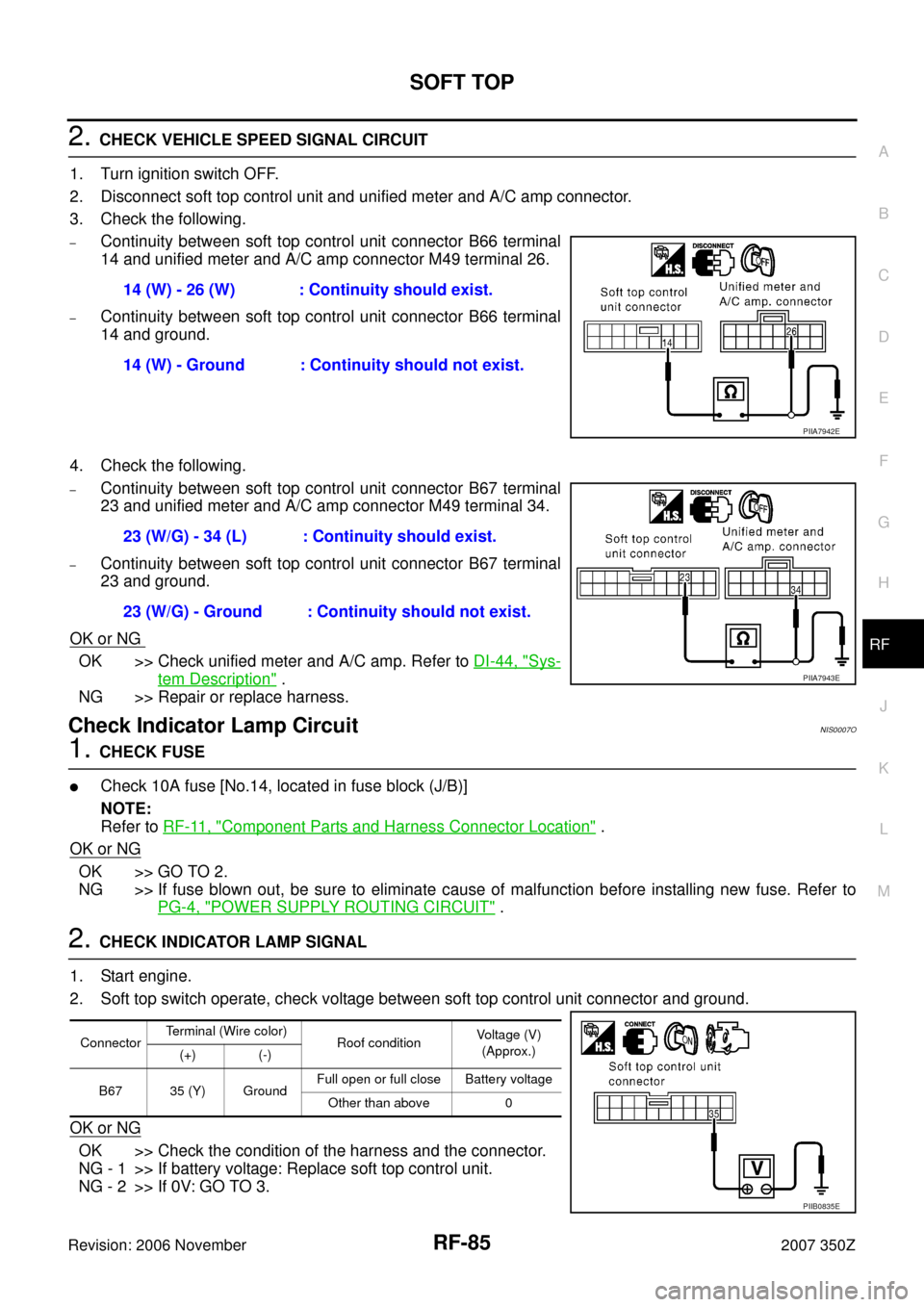
1. CHECK SEAT BACK POSITION SIGNAL
1. Start engine.
2. The thing whose seat cancel switch is OFF is confirmed.
3. Soft top switch operate, check voltage between soft top control unit connector and ground.
OK or NG
OK >> Replace soft top control unit.
NG >> GO TO 2.13 (L/R) - 33 (G/B) : Continuity should exist.
13 (L/R) - Ground : Continuity should not exist.
PIIA7959E
11 (L/W) - 30 (Y/R) : Continuity should exist.
11 (L/W) - Ground : Continuity should not exist.
PIIB9257E
ConnectorTerminal (Wire color)
Seat conditionVoltage (V)
(Approx.)
(+) (-)
B67 34 (L/W) GroundWhen passenger seat
inclines forward5
Other than above 0
PIIA7961E
Page 84 of 130

RF-84
SOFT TOP
Revision: 2006 November2007 350Z
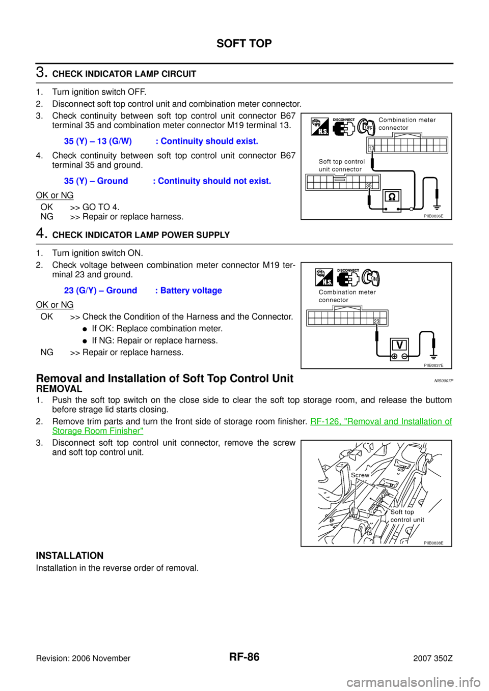
2. CHECK SEAT BACK POSITION SIGNAL CIRCUIT
1. Turn ignition switch OFF.
2. Disconnect soft top control unit and passenger seat control unit connector.
3. Check continuity between soft top control unit connector B67
terminal 34 and passenger seat control unit connector B353 ter-
minal 32.
4. Check continuity between soft top control unit connector B67
terminal 34 and ground.
OK or NG
OK >> Check passenger side seat. Refer to SE-37, "Trouble
Diagnosis Symptom Chart" .
NG >> Repair or replace harness.
Check Speed Signal CircuitNIS0007N
First perform the “SELF-DIAG RESULT” in “BCM” with CONSULT-II, then perform the each trouble diagnosis
of malfunction system indicated “SELF-DIAG RESULT” of “BCM”. Refer to BCS-15, "
CONSULT-III Function
(BCM)" .
1. CHECK VEHICLE SPEED SIGNAL
1. Start engine.
2. Check the signal between soft top control unit connector and ground with oscilloscope.
OK or NG
OK >> Replace soft top control unit.
NG >> GO TO 2.34 (L/W) - 32 (G/W) : Continuity should exist.
34 (L/W) - Ground : Continuity should not exist.
PIIA7962E
ConnectorTerminal (Wire
color)
ConditionSignal
(Reference value.)
(+) (-)
B66 14 (W)
GroundSpeedometer
operated
[When
vehicle speed
is Approx.
40km/h
(25MPH)]
B67 23 (W/G)
PIIA7941EPKIA1935E
PIIB0078J
Page 85 of 130

SOFT TOP
RF-85
C
D
E
F
G
H
J
K
L
MA
B
RF
Revision: 2006 November2007 350Z
2. CHECK VEHICLE SPEED SIGNAL CIRCUIT
1. Turn ignition switch OFF.
2. Disconnect soft top control unit and unified meter and A/C amp connector.
3. Check the following.
–Continuity between soft top control unit connector B66 terminal
14 and unified meter and A/C amp connector M49 terminal 26.
–Continuity between soft top control unit connector B66 terminal
14 and ground.
4. Check the following.
–Continuity between soft top control unit connector B67 terminal
23 and unified meter and A/C amp connector M49 terminal 34.
–Continuity between soft top control unit connector B67 terminal
23 and ground.
OK or NG
OK >> Check unified meter and A/C amp. Refer to DI-44, "Sys-
tem Description" .
NG >> Repair or replace harness.
Check Indicator Lamp CircuitNIS0007O
1. CHECK FUSE
�Check 10A fuse [No.14, located in fuse block (J/B)]
NOTE:
Refer to RF-11, "
Component Parts and Harness Connector Location" .
OK or NG
OK >> GO TO 2.
NG >> If fuse blown out, be sure to eliminate cause of malfunction before installing new fuse. Refer to
PG-4, "
POWER SUPPLY ROUTING CIRCUIT" .
2. CHECK INDICATOR LAMP SIGNAL
1. Start engine.
2. Soft top switch operate, check voltage between soft top control unit connector and ground.
OK or NG
OK >> Check the condition of the harness and the connector.
NG - 1 >> If battery voltage: Replace soft top control unit.
NG - 2 >> If 0V: GO TO 3.14 (W) - 26 (W) : Continuity should exist.
14 (W) - Ground : Continuity should not exist.
PIIA7942E
23 (W/G) - 34 (L) : Continuity should exist.
23 (W/G) - Ground : Continuity should not exist.
PIIA7943E
ConnectorTerminal (Wire color)
Roof conditionVoltage (V)
(Approx.)
(+) (-)
B67 35 (Y) GroundFull open or full close Battery voltage
Other than above 0
PIIB0835E
Page 86 of 130

RF-86
SOFT TOP
Revision: 2006 November2007 350Z
3. CHECK INDICATOR LAMP CIRCUIT
1. Turn ignition switch OFF.
2. Disconnect soft top control unit and combination meter connector.
3. Check continuity between soft top control unit connector B67
terminal 35 and combination meter connector M19 terminal 13.
4. Check continuity between soft top control unit connector B67
terminal 35 and ground.
OK or NG
OK >> GO TO 4.
NG >> Repair or replace harness.
4. CHECK INDICATOR LAMP POWER SUPPLY
1. Turn ignition switch ON.
2. Check voltage between combination meter connector M19 ter-
minal 23 and ground.
OK or NG
OK >> Check the Condition of the Harness and the Connector.
�If OK: Replace combination meter.
�If NG: Repair or replace harness.
NG >> Repair or replace harness.
Removal and Installation of Soft Top Control UnitNIS0007P
REMOVAL
1. Push the soft top switch on the close side to clear the soft top storage room, and release the buttom
before strage lid starts closing.
2. Remove trim parts and turn the front side of storage room finisher. RF-126, "
Removal and Installation of
Storage Room Finisher"
3. Disconnect soft top control unit connector, remove the screw
and soft top control unit.
INSTALLATION
Installation in the reverse order of removal.35 (Y) – 13 (G/W) : Continuity should exist.
35 (Y) – Ground : Continuity should not exist.
PIIB0836E
23 (G/Y) – Ground : Battery voltage
PIIB0837E
PIIB0838E