RAX-6
WHEEL HUB
Revision: 2006 November2007 350Z
WHEEL HUBPFP:43202
On-Vehicle InspectionNDS0000X
Make sure the mounting conditions (looseness, back lash) of each component and component status (wear,
damage) are normal.
WHEEL BEARING INSPECTION
�Move wheel hub in the axial direction by hand. Make sure there is no looseness of wheel bearing.
�Rotate wheel hub and make sure there is no unusual noise or other irregular conditions. If there are any
irregular conditions, replace wheel bearings.
Removal and InstallationNDS0000Y
COMPONENT
REMOVAL
1. Remove tires from vehicle with power tool.
2. Remove cotter pin. Then remove lock nut from drive shaft.
3. Remove brake caliper with power tool. Hang it in a place where it will not interfere with work. Refer to BR-
39, "REAR DISC BRAKE" .
NOTE:
Avoid depressing brake pedal while brake caliper is removed.
4. Remove disc rotor and remove parking cable and parking brake shoe from back plate. Refer to PB-4,
"PARKING BRAKE CONTROL" , PB-5, "PARKING BRAKE SHOE" .
5. Remove fixing bolts and nuts in axle side of radius rod, front lower link with power tool.
6. Remove fixing bolt and nut in axle side of rear lower link with power tool. Then remove coil spring. Refer to
RSU-15, "
REAR LOWER LINK & COIL SPRING" .
7. Remove fixing bolt and nut in axle side of shock absorber with power tool.
8. Using a puller (suitable tool), remove axle from drive shaft.
CAUTION:
�When removing axle, do not apply an excessive angle to drive shaft joint. Also be careful not to
excessively extend slide joint. Axial end play : 0.05 mm (0.002 in) or less
1. Drive shaft 2. Dust shield 3. Ball seat
4. Bushing 5. Cotter pin 6. Axle housing
7. Back plate 8. Anchor block 9. Wheel bearing
10. Wheel hub
Refer to GI-11, "
Components" , for the symbols in the figure.
SDIA3577E
WHEEL HUB
RAX-7
C
E
F
G
H
I
J
K
L
MA
B
RAX
Revision: 2006 November2007 350Z
�Do not allow drive shaft to hang down without support for counter shaft, wheel joints, and other
parts.
9. Remove suspension arm and cotter pin at axle, then loosen mounting nut.
10. Use a ball joint remover (suitable tool) to remove suspension arm from axle. Be careful not to damage ball
joint boot.
CAUTION:
Tighten temporarily mounting nut to prevent damage to threads and to prevent ball joint remover
(suitable tool) from coming off.
INSPECTION AFTER REMOVAL
Ball Joint Inspection
�Check for boot breakage, axial looseness, and torque of suspension arm ball joint. Refer to RSU-11,
"SUSPENSION ARM" .
INSTALLATION
�Refer to RAX-6, "Removal and Installation" for tightening torque. Install in the reverse order of removal.
NOTE:
Refer to component parts location and do not reuse non-reusable parts.
Disassembly and AssemblyNDS0000Z
DISASSEMBLY
Wheel Bearing
CAUTION:
Do not disassemble if wheel bearing has no trouble.
1. Remove wheel bearing fixing bolts and anchor block fixing nuts, and remove wheel hub and bearing
assembly, back plate and anchor block from axle.
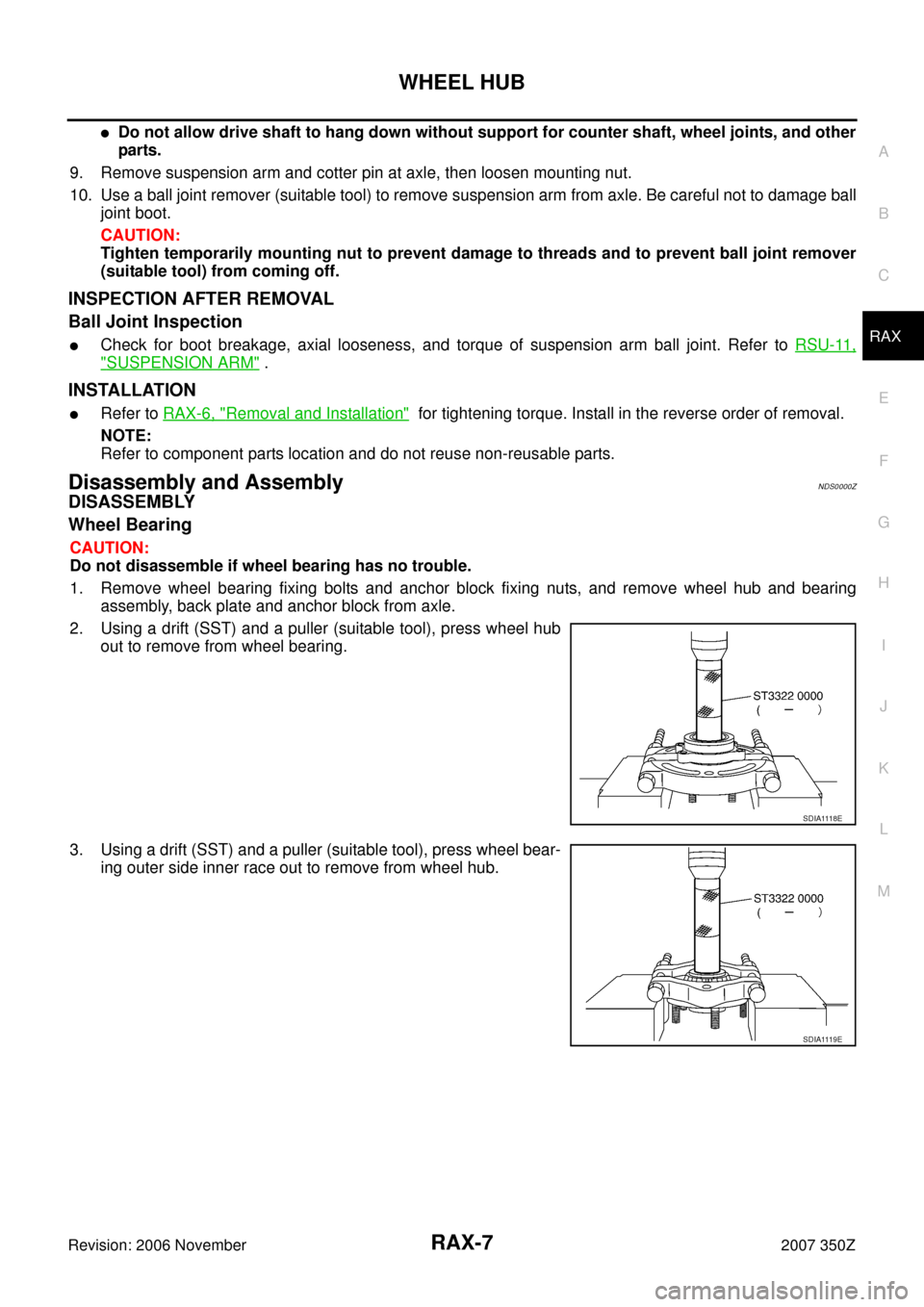
2. Using a drift (SST) and a puller (suitable tool), press wheel hub
out to remove from wheel bearing.
3. Using a drift (SST) and a puller (suitable tool), press wheel bear-
ing outer side inner race out to remove from wheel hub.
SDIA1118E
SDIA1119E
 of each component and component status (wear,")