Page 5 of 16

NOISE, VIBRATION AND HARSHNESS (NVH) TROUBLESHOOTING
RAX-5
C
E
F
G
H
I
J
K
L
MA
B
RAX
Revision: 2006 November2007 350Z
NOISE, VIBRATION AND HARSHNESS (NVH) TROUBLESHOOTINGPFP:00003
NVH Troubleshooting ChartNDS0000W
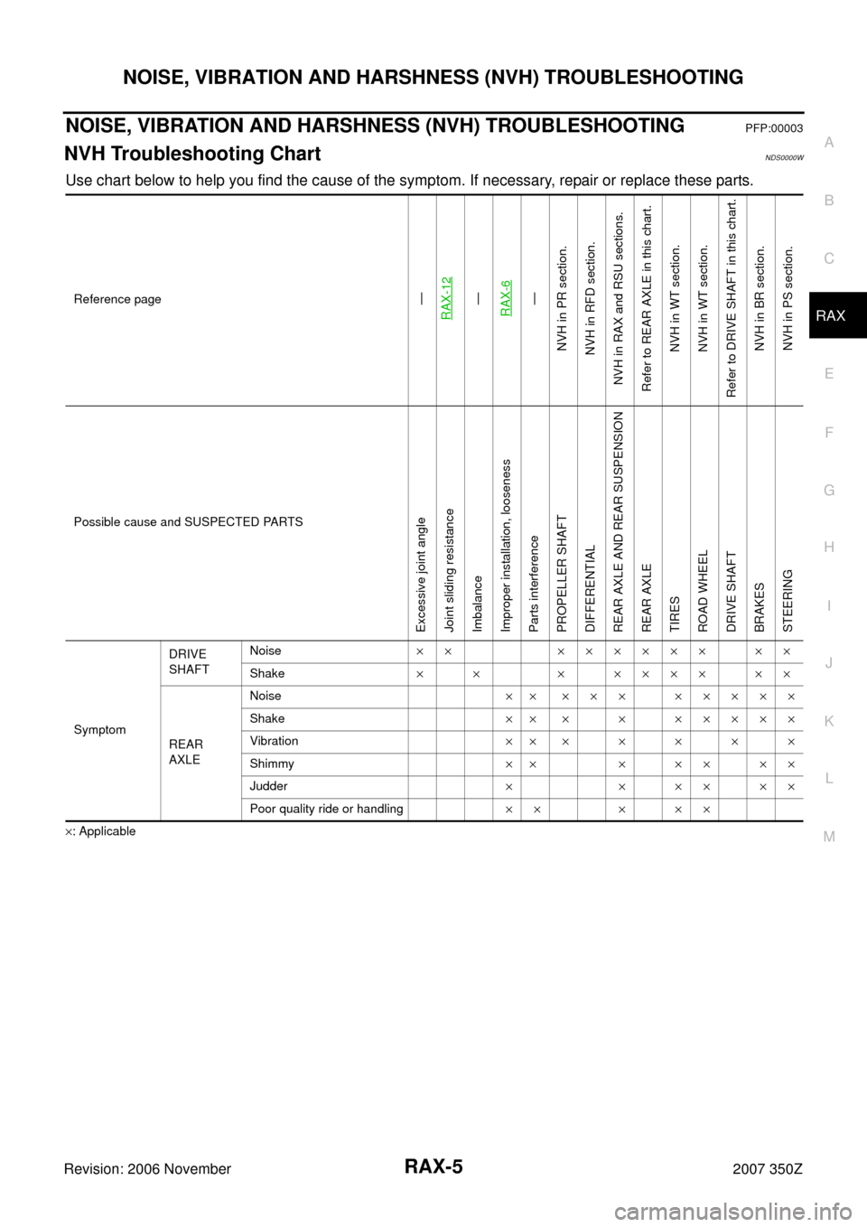
Use chart below to help you find the cause of the symptom. If necessary, repair or replace these parts.
×: ApplicableReference page
—
RAX-12—
RAX-6—
NVH in PR section.
NVH in RFD section.
NVH in RAX and RSU sections.
Refer to REAR AXLE in this chart.
NVH in WT section.
NVH in WT section.
Refer to DRIVE SHAFT in this chart.
NVH in BR section.
NVH in PS section.
Possible cause and SUSPECTED PARTS
Excessive joint angle
Joint sliding resistance
Imbalance
Improper installation, looseness
Parts interference
PROPELLER SHAFT
DIFFERENTIAL
REAR AXLE AND REAR SUSPENSION
REAR AXLE
TIRES
ROAD WHEEL
DRIVE SHAFT
BRAKES
STEERING
SymptomDRIVE
SHAFTNoise×× ×××××× ××
Shake×× ×××××××
REAR
AXLENoise×× ××× ×××××
Shake×× × × ×××××
Vibration×××××××
Shimmy×× × × × × ×
Judder××××××
Poor quality ride or handling×× × ××
Page 6 of 16

RAX-6
WHEEL HUB
Revision: 2006 November2007 350Z
WHEEL HUBPFP:43202
On-Vehicle InspectionNDS0000X
Make sure the mounting conditions (looseness, back lash) of each component and component status (wear,
damage) are normal.
WHEEL BEARING INSPECTION
�Move wheel hub in the axial direction by hand. Make sure there is no looseness of wheel bearing.
�Rotate wheel hub and make sure there is no unusual noise or other irregular conditions. If there are any
irregular conditions, replace wheel bearings.
Removal and InstallationNDS0000Y
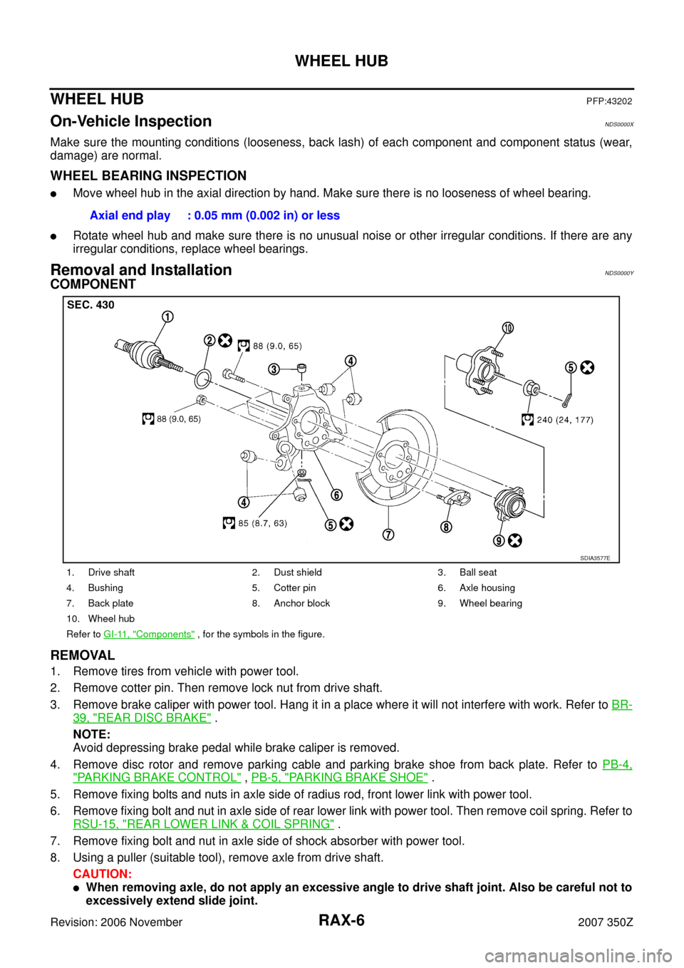
COMPONENT
REMOVAL
1. Remove tires from vehicle with power tool.
2. Remove cotter pin. Then remove lock nut from drive shaft.
3. Remove brake caliper with power tool. Hang it in a place where it will not interfere with work. Refer to BR-
39, "REAR DISC BRAKE" .
NOTE:
Avoid depressing brake pedal while brake caliper is removed.
4. Remove disc rotor and remove parking cable and parking brake shoe from back plate. Refer to PB-4,
"PARKING BRAKE CONTROL" , PB-5, "PARKING BRAKE SHOE" .
5. Remove fixing bolts and nuts in axle side of radius rod, front lower link with power tool.
6. Remove fixing bolt and nut in axle side of rear lower link with power tool. Then remove coil spring. Refer to
RSU-15, "
REAR LOWER LINK & COIL SPRING" .
7. Remove fixing bolt and nut in axle side of shock absorber with power tool.
8. Using a puller (suitable tool), remove axle from drive shaft.
CAUTION:
�When removing axle, do not apply an excessive angle to drive shaft joint. Also be careful not to
excessively extend slide joint. Axial end play : 0.05 mm (0.002 in) or less
1. Drive shaft 2. Dust shield 3. Ball seat
4. Bushing 5. Cotter pin 6. Axle housing
7. Back plate 8. Anchor block 9. Wheel bearing
10. Wheel hub
Refer to GI-11, "
Components" , for the symbols in the figure.
SDIA3577E
Page 15 of 16

REAR DRIVE SHAFT
RAX-15
C
E
F
G
H
I
J
K
L
MA
B
RAX
Revision: 2006 November2007 350Z
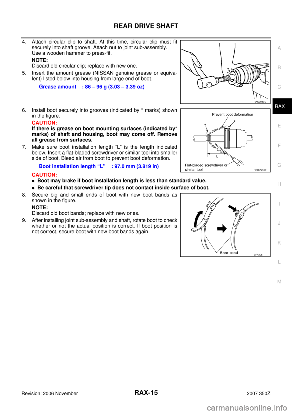
4. Attach circular clip to shaft. At this time, circular clip must fit
securely into shaft groove. Attach nut to joint sub-assembly.
Use a wooden hammer to press-fit.
NOTE:
Discard old circular clip; replace with new one.
5. Insert the amount grease (NISSAN genuine grease or equiva-
lent) listed below into housing from large end of boot.
6. Install boot securely into grooves (indicated by * marks) shown
in the figure.
CAUTION:
If there is grease on boot mounting surfaces (indicated by*
marks) of shaft and housing, boot may come off. Remove
all grease from surfaces.
7. Make sure boot installation length “L” is the length indicated
below. Insert a flat-bladed screwdriver or similar tool into smaller
side of boot. Bleed air from boot to prevent boot deformation.
CAUTION:
�Boot may brake if boot installation length is less than standard value.
�Be careful that screwdriver tip does not contact inside surface of boot.
8. Secure big and small ends of boot with new boot bands as
shown in the figure.
NOTE:
Discard old boot bands; replace with new ones.
9. After installing joint sub-assembly and shaft, rotate boot to check
whether or not the actual position is correct. If boot position is
not correct, secure boot with new boot bands again.Grease amount : 86 – 96 g (3.03 – 3.39 oz)
RAC0049D
Boot installation length “L” : 97.0 mm (3.819 in)SDIA2491E
SFA395
Page 16 of 16
RAX-16
SERVICE DATA AND SPECIFICATIONS (SDS)
Revision: 2006 November2007 350Z
SERVICE DATA AND SPECIFICATIONS (SDS)PFP:00030
Wheel BearingNDS00012
Drive ShaftNDS00013
Axial end play0.05 mm (0.002 in) or less
Rotating torqueAt a load of 49,033 N (5,000 kg, 11,000 lb)
Less than 1.88 N·m (0.19 kg-m, 17 in-lb)
Measurement of spring balance Less than 18.5 N (1.89 kg, 4.16 lb)
Measuring point (Brake caliper installation points)
SDIA0801E
Joint Wheel side Final drive side
Grease quantity 86 – 96 g (3.03 – 3.39 oz) 124 – 134 g (4.37 – 4.73 oz)
Boots installed length 97.0 mm (3.819 in) 93.9 mm (3.697 in)