Page 9 of 86
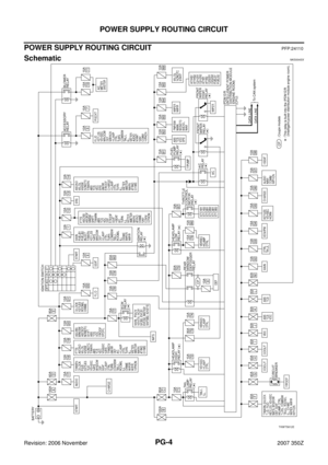
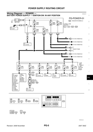
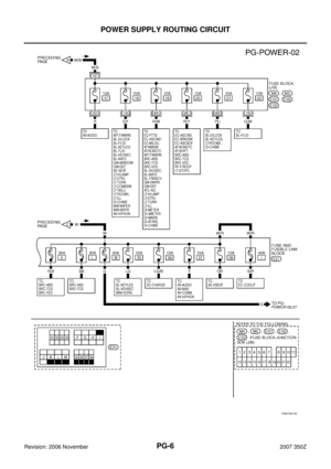
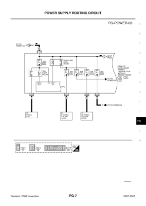
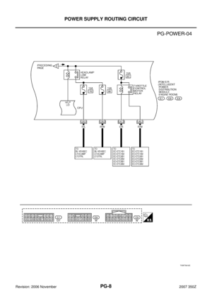
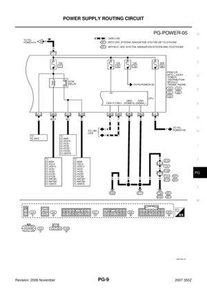
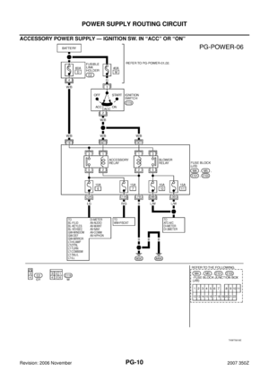
POWER SUPPLY ROUTING CIRCUIT
PG-9
C
D
E
F
G
H
I
J
L
MA
B
PG
Revision: 2006 November2007 350Z
TKWT5817E
Page 10 of 86
PG-10
POWER SUPPLY ROUTING CIRCUIT
Revision: 2006 November2007 350Z
ACCESSORY POWER SUPPLY — IGNITION SW. IN “ACC” OR “ON”
TKWT5818E
Page 11 of 86
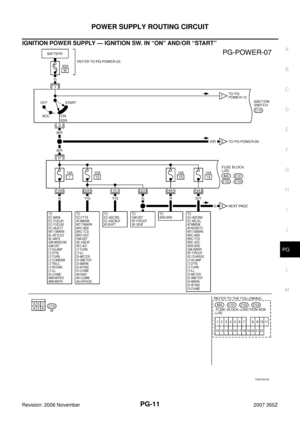
POWER SUPPLY ROUTING CIRCUIT
PG-11
C
D
E
F
G
H
I
J
L
MA
B
PG
Revision: 2006 November2007 350Z
IGNITION POWER SUPPLY — IGNITION SW. IN “ON” AND/OR “START”
TKWT5819E
Page 12 of 86
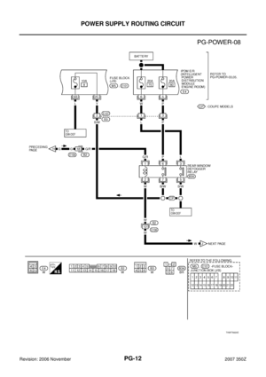
PG-12
POWER SUPPLY ROUTING CIRCUIT
Revision: 2006 November2007 350Z
TKWT5820E
Page 13 of 86
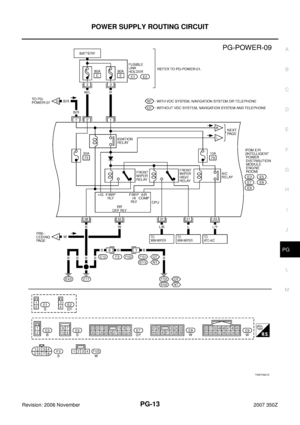
POWER SUPPLY ROUTING CIRCUIT
PG-13
C
D
E
F
G
H
I
J
L
MA
B
PG
Revision: 2006 November2007 350Z
TKWT5821E
Page 14 of 86
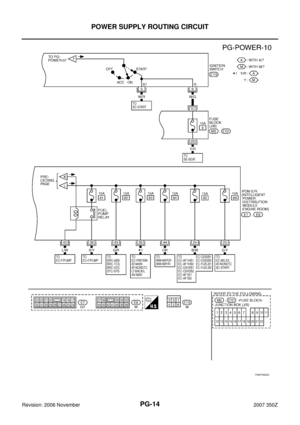
PG-14
POWER SUPPLY ROUTING CIRCUIT
Revision: 2006 November2007 350Z
TKWT5822E
Page 15 of 86

POWER SUPPLY ROUTING CIRCUIT
PG-15
C
D
E
F
G
H
I
J
L
MA
B
PG
Revision: 2006 November2007 350Z
Fuse NKS000E1
�If fuse is blown, be sure to eliminate cause of malfunction before
installing new fuse.
�Use fuse of specified rating. Never use fuse of more than speci-
fied rating.
�Do not partially install fuse; always insert it into fuse holder prop-
erly.
�Remove fuse for “ELECTRICAL PARTS (BAT)” if vehicle is not
used for a long period of time.
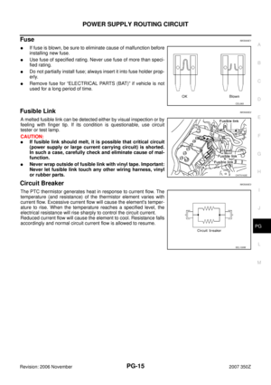
Fusible Link NKS000E2
A melted fusible link can be detected either by visual inspection or by
feeling with finger tip. If its condition is questionable, use circuit
tester or test lamp.
CAUTION:
�If fusible link should melt, it is possible that critical circuit
(power supply or large current carrying circuit) is shorted.
In such a case, carefully check and eliminate cause of mal-
function.
�Never wrap outside of fusible link with vinyl tape. Important:
Never let fusible link touch any other wiring harness, vinyl
or rubber parts.
Circuit Breaker NKS000E3
The PTC thermistor generates heat in response to current flow. The
temperature (and resistance) of the thermistor element varies with
current flow. Excessive current flow will cause the element's temper-
ature to rise. When the temperature reaches a specified level, the
electrical resistance will rise sharply to control the circuit current.
Reduced current flow will cause the element to cool. Resistance falls
accordingly and normal circuit current flow is allowed to resume.
CEL083
CKIT0163E
SEL109W
Page 16 of 86

Revision: 2006 November2007 350Z
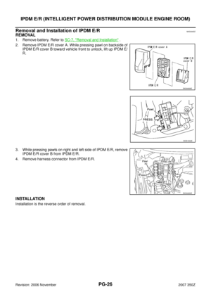
IPDM E/R (INTELLIGENT POWER DISTRIBUTION MODULE ENGINE ROOM)
PFP:284B7
System DescriptionNKS000E4
�I")
PG-16
IPDM E/R (INTELLIGENT POWER DISTRIBUTION MODULE ENGINE ROOM)
Revision: 2006 November2007 350Z
IPDM E/R (INTELLIGENT POWER DISTRIBUTION MODULE ENGINE ROOM)
PFP:284B7
System DescriptionNKS000E4
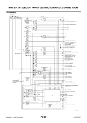
�IPDM E/R (Intelligent Power Distribution Module Engine Room) integrates relays and fuse blocks which
were originally placed in engine room. It controls integrated relays via IPDM E/R control circuit.
�IPDM E/R integrated control unit performs ON-OFF operation of relay, hood switch signal reception, etc.
�It controls operation of each electrical part via ECM, BCM and CAN communication lines.
CAUTION:
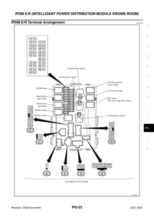
None of the IPDM E/R-integrated relays can be removed.
SYSTEMS CONTROLLED BY IPDM E/R
IPDM E/R receives a request signal from each control unit with CAN communication. It controls each system.
CAN COMMUNICATION LINE CONTROL
With CAN communication, by connecting each control unit using two communication lines (CAN L line, CAN H
line), it is possible to transmit maximum amount of information with minimum wiring. Each control unit can
transmit and receive data, and reads necessary information only.
1. Fail-safe control
�When CAN communication with other control units is impossible, IPDM E/R performs fail-safe control.
After CAN communication recovers normally, it also returns to normal control.
�Operation of control parts by IPDM E/R during fail-safe mode is as follows:
Control system Transmit control unit Control part
Lamp control BCM
�Head lamps (HI, LO)
�Parking lamps, license plate lamps and tail lamps
Wiper control BCM Front wipers
Rear window defogger control BCM Rear window defogger
A/C compressor control ECM A/C compressor (magnet clutch)
Cooling fan control ECM Cooling fan
Controlled system Fail-safe mode
Headlamp
�With the ignition switch ON, the headlamp (low) is ON.
�With the ignition switch OFF, the headlamp (low) is OFF.
Parking, license plate and tail lamps
�With the ignition switch ON, the parking, license plate and tail lamps are ON.
�With the ignition switch OFF, the parking, license plate and tail lamps are OFF.
Cooling fan
�With the ignition switch ON, the cooling fan HI operates.
�With the ignition switch OFF, the cooling fan stops.
Front wiperUntil the ignition switch is turned OFF, the front wiper LO and HI remains in the same status
it was in just before fail−safe control was initiated.
Rear window defogger Rear window defogger relay OFF
A/C compressor A/C compressor OFF