Page 7 of 62
DESCRIPTION
MT-7
D
E
F
G
H
I
J
K
L
MA
B
MT
Revision: 2006 November2007 350Z
DESCRIPTIONPFP:00000
Cross-Sectional ViewNCS0000S
1. Front cover 2. Main drive gear 3. Counter shaft
4. 6th counter gear 5. 2nd counter gear 6. 1st counter gear
7. 3rd counter gear 8. 3rd-4th synchronizer hub 9. 3rd-4th coupling sleeve
10. 4th counter gear 11. Adapter plate 12. Reverse idler gear
13. Reverse idler shaft 14. Reverse counter gear 15. Main shaft
16. Rear extension 17. Striking rod 18. Reverse synchronizer hub
19. Reverse coupling sleeve 20. Reverse main gear 21. 4th main gear
22. 3rd main gear 23. 1st main gear 24. 1st-2nd coupling sleeve
25. 1st-2nd synchronizer hub 26. 2nd main gear 27. 6th main gear
28. Transmission case 29. 5th-6th coupling sleeve 30. 5th-6th synchronizer hub
PCIB1912E
Page 10 of 62
MT-10
REAR OIL SEAL
Revision: 2006 November2007 350Z
REAR OIL SEALPFP:33140
Removal and InstallationNCS0000V
REMOVAL
1. Remove propeller shaft. Refer to PR-6, "Removal and Installa-
tion" .
CAUTION:
Do not impact or damage propeller shaft tube.
2. Remove rear oil seal using oil seal puller.
INSTALLATION
1. Apply multi-purpose grease to rear oil seal lip. Drive in rear oil
seal until the edge is approximately 1.2 - 2.2 mm (0.047 - 0.087
in) above the boss edge using drift.
CAUTION:
�Do not reuse rear oil seal.
�When installing, do not incline the rear oil seal.
2. Install propeller shaft. Refer to PR-6, "
Removal and Installation" .
CAUTION:
�Do not impact or damage propeller shaft tube.
�If lubricant leak has occurred, after finishing work, check oil level. Refer to MT-9, "Checking M/T
Oil" . Tool number : KV381054S0 (J-34286)
PCIB0194E
Tool number : ST33400001 (J-26082)
PCIB0595E
Page 21 of 62

TRANSMISSION ASSEMBLY
MT-21
D
E
F
G
H
I
J
K
L
MA
B
MT
Revision: 2006 November2007 350Z
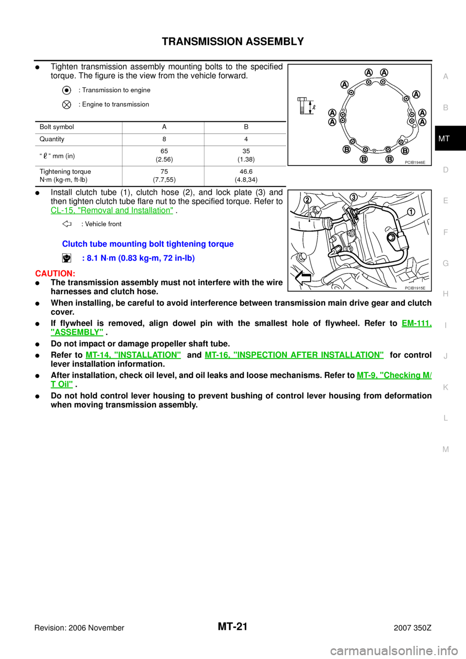
�Tighten transmission assembly mounting bolts to the specified
torque. The figure is the view from the vehicle forward.
�Install clutch tube (1), clutch hose (2), and lock plate (3) and
then tighten clutch tube flare nut to the specified torque. Refer to
CL-15, "
Removal and Installation" .
CAUTION:
�The transmission assembly must not interfere with the wire
harnesses and clutch hose.
�When installing, be careful to avoid interference between transmission main drive gear and clutch
cover.
�If flywheel is removed, align dowel pin with the smallest hole of flywheel. Refer to EM-111,
"ASSEMBLY" .
�Do not impact or damage propeller shaft tube.
�Refer to MT-14, "INSTALLATION" and MT-16, "INSPECTION AFTER INSTALLATION" for control
lever installation information.
�After installation, check oil level, and oil leaks and loose mechanisms. Refer to MT-9, "Checking M/
T Oil" .
�Do not hold control lever housing to prevent bushing of control lever housing from deformation
when moving transmission assembly.
: Transmission to engine
: Engine to transmission
Bolt symbol A B
Quantity 8 4
“” mm (in)65
(2.56)35
(1.38)
Tightening torque
N·m (kg-m, ft-lb)75
(7.7,55)46.6
(4.8,34)
: Vehicle front
Clutch tube mounting bolt tightening torque
: 8.1 N·m (0.83 kg-m, 72 in-lb)
PCIB1946E
PCIB1915E
Page 24 of 62

MT-24
TRANSMISSION ASSEMBLY
Revision: 2006 November2007 350Z
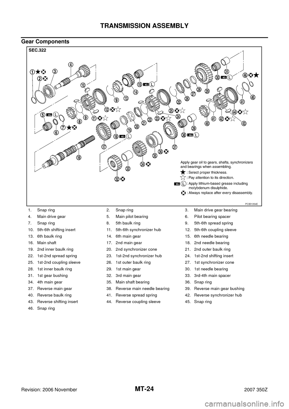
Gear Components
1. Snap ring 2. Snap ring 3. Main drive gear bearing
4. Main drive gear 5. Main pilot bearing 6. Pilot bearing spacer
7. Snap ring 8. 5th baulk ring 9. 5th-6th spread spring
10. 5th-6th shifting insert 11. 5th-6th synchronizer hub 12. 5th-6th coupling sleeve
13. 6th baulk ring 14. 6th main gear 15. 6th needle bearing
16. Main shaft 17. 2nd main gear 18. 2nd needle bearing
19. 2nd inner baulk ring 20. 2nd synchronizer cone 21. 2nd outer baulk ring
22. 1st-2nd spread spring 23. 1st-2nd synchronizer hub 24. 1st-2nd shifting insert
25. 1st-2nd coupling sleeve 26. 1st outer baulk ring 27. 1st synchronizer cone
28. 1st inner baulk ring 29. 1st main gear 30. 1st needle bearing
31. 1st gear bushing 32. 3rd main gear 33. 3rd-4th main spacer
34. 4th main gear 35. Main shaft bearing 36. Snap ring
37. Reverse main gear 38. Reverse main needle bearing 39. Reverse main gear bushing
40. Reverse baulk ring 41. Reverse spread spring 42. Reverse synchronizer hub
43. Reverse shifting insert 44. Reverse coupling sleeve 45. Snap ring
46. Snap ring
PCIB1354E
Page 29 of 62

TRANSMISSION ASSEMBLY
MT-29
D
E
F
G
H
I
J
K
L
MA
B
MT
Revision: 2006 November2007 350Z
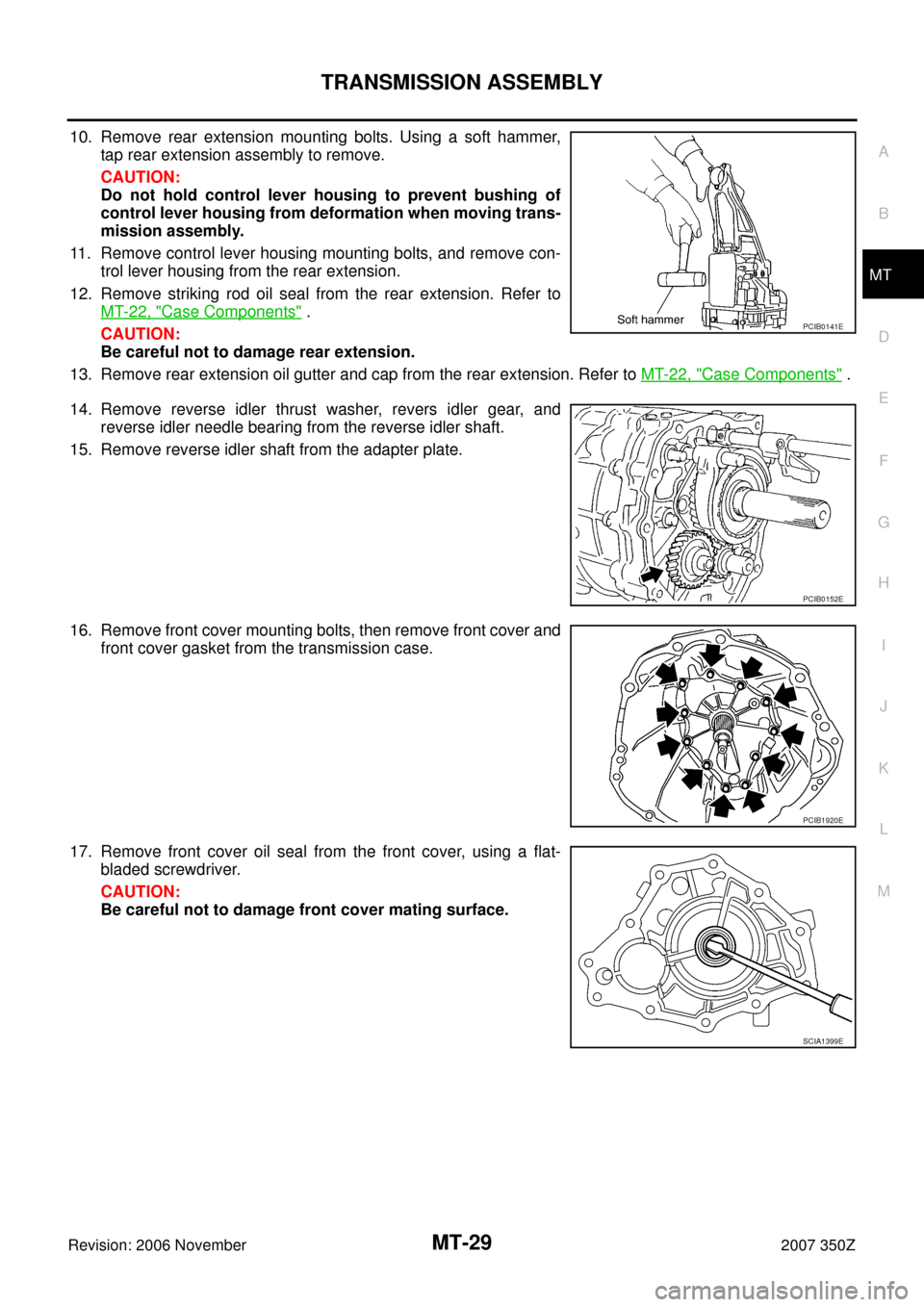
10. Remove rear extension mounting bolts. Using a soft hammer,
tap rear extension assembly to remove.
CAUTION:
Do not hold control lever housing to prevent bushing of
control lever housing from deformation when moving trans-
mission assembly.
11. Remove control lever housing mounting bolts, and remove con-
trol lever housing from the rear extension.
12. Remove striking rod oil seal from the rear extension. Refer to
MT-22, "
Case Components" .
CAUTION:
Be careful not to damage rear extension.
13. Remove rear extension oil gutter and cap from the rear extension. Refer to MT-22, "
Case Components" .
14. Remove reverse idler thrust washer, revers idler gear, and
reverse idler needle bearing from the reverse idler shaft.
15. Remove reverse idler shaft from the adapter plate.
16. Remove front cover mounting bolts, then remove front cover and
front cover gasket from the transmission case.
17. Remove front cover oil seal from the front cover, using a flat-
bladed screwdriver.
CAUTION:
Be careful not to damage front cover mating surface.
PCIB0141E
PCIB0152E
PCIB1920E
SCIA1399E
Page 30 of 62
MT-30
TRANSMISSION ASSEMBLY
Revision: 2006 November2007 350Z
18. Remove baffle plate mounting nut from the transmission case.
19. Remove snap ring from the main drive gear bearing, using snap
ring pliers.
20. Using a soft hammer to carefully tap main shaft and counter
shaft from the transmission case side, and then separate
adapter plate and transmission case.
21. Remove counter front bearing from the transmission case.
22. Remove oil gutter and breather tube from the transmission case.
23. Remove filler plug, drain plug, and gaskets from transmission
case.
24. Remove bracket mounting bolt and then remove bracket from
transmission case.
SCIA1443E
SCIA1532E
SCIA1687E
PCIB0436E
Page 34 of 62
MT-34
TRANSMISSION ASSEMBLY
Revision: 2006 November2007 350Z
15. Using a pin punch to knock out retaining pin, and then remove
5th-6th fork rod bracket and 5th-6th fork rod.
16. Using a pin punch to knock out retaining pin, and then remove
5th-6th fork rod (reversal side) and 5th-6th shift fork.
Gear Components
�Before disassembly, measure end play for each position. If the end play is outside the standards, disas-
semble and inspect.
–Main drive gear
–Main shaft
PCIB0239E
PCIB0412E
End play : 0 - 0.10 mm (0 - 0.004 in)
PCIB0484E
End play : 0 - 0.10 mm (0 - 0.004 in)
PCIB0225E
Page 36 of 62
MT-36
TRANSMISSION ASSEMBLY
Revision: 2006 November2007 350Z
6. Carefully tap main shaft with a plastic hammer and then remove
main shaft, main drive gear, and counter shaft from adapter
plate.
7. Remove main pilot bearing, pilot bearing spacer and 5th baulk
ring.
8. Remove counter rear bearing from the adapter plate.
9. Remove magnet from adapter plate.
10. Remove snap ring from the main drive gear using snap ring pli-
ers.
11. Set the suitable puller on the main drive gear and then using a
press to remove main drive gear bearing from the main drive
gear.
12. Using a press to remove the reverse main gear bushing, main
shaft bearing and 4th main gear.
13. Remove 3rd-4th main spacer.
SCIA1456E
PCIB0244E
SCIA1461E
SCIA1533E
SCIA1386E