Page 17 of 30
:
Unit: (US qt, lmp qt)
CAUTION:
�When filling engine oil, do not pull out oil l")
ENGINE MAINTENANCE
MA-17
C
D
E
F
G
H
I
J
K
MA
B
MA
Revision: 2006 November2007 350Z
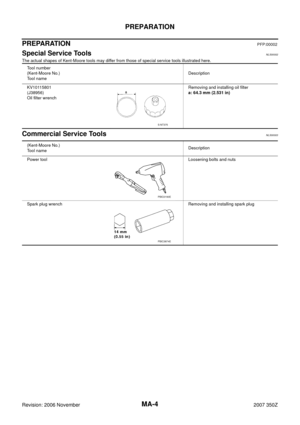
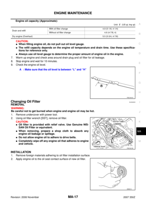
Engine oil capacity (Approximate):
Unit: (US qt, lmp qt)
CAUTION:
�When filling engine oil, do not pull out oil level gauge.
�The refill capacity depends on the engine oil temperature and drain time. Use these specifica-
tions for reference only.
�Always use oil level gauge to determine the proper amount of engine oil in the engine.
7. Warm up engine and check area around drain plug and oil filter for oil leakage.
8. Stop engine and wait for 10 minutes.
9. Check the engine oil level.
Changing Oil FilterNLS0000G
REMOVAL
WARNING:
Be careful not to get burned when engine and engine oil may be hot.
1. Remove undercover with power tool.
2. Using oil filter wrench [SST], remove oil filter.
CAUTION:
�Oil filter is provided with relief valve. Use Genuine NIS-
SAN Oil Filter or equivalent.
�When removing, prepare a shop cloth to absorb any
engine oil leakage or spillage.
�Do not allow engine oil to adhere to drive belts.
�Completely wipe off any engine oil that adheres to engine
and vehicle.
INSTALLATION
1. Remove foreign materials adhering to oil filter installation surface.
2. Apply engine oil to the oil seal contact surface of new oil filter.
Drain and refill With oil filter change 4.9 (5-1/8, 4-1/4)
Without oil filter change 4.6 (4-7/8, 4)
Dry engine (Overhaul)5.5 (5-3/4, 4-7/8)
A : Make sure that the oil level is between “L” and “H”
PBIC4931E
PBIC0819E
SMA010
Page 18 of 30

MA-18
ENGINE MAINTENANCE
Revision: 2006 November2007 350Z
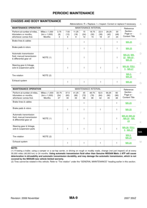
3. Screw oil filter manually until it touches the installation surface,
then tighten it by 2/3 turn. Or tighten to specification.
INSPECTION AFTER INSTALLATION
1. Check the engine oil level. Refer to MA-16, "Changing Engine Oil" .
2. Start engine, and check there is no leak of engine oil.
3. Stop engine and wait for 10 minutes.
4. Check the engine oil level and adjust engine oil. Refer to MA-16, "
Changing Engine Oil" .
Changing Spark Plugs (Iridium-Tipped Type)NLS0000H
REMOVAL
1. Remove engine cover with power tool. Refer to EM-17, "INTAKE MANIFOLD COLLECTOR" .
2. Remove ignition coil. Refer to EM-31, "
IGNITION COIL" .
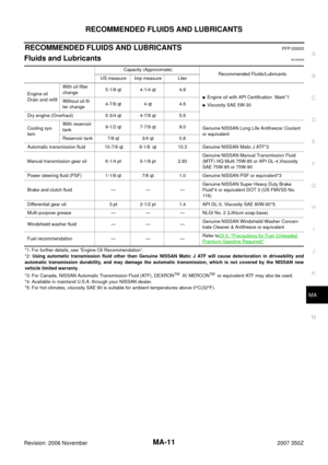
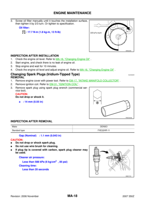
3. Remove spark plug using spark plug wrench (commercial ser-
vice tool).
CAUTION:
Do not drop or shock it.
INSPECTION AFTER REMOVAL
CAUTION:
�Do not drop or shock spark plug.
�Do not use wire brush for cleaning.
�If plug tip is covered with carbon, spark plug cleaner may
be used.Oil filter:
: 17.7 N·m (1.8 kg-m, 13 ft-lb)
SMA229B
a : 14 mm (0.55 in)
PBIC5043E
MakeDENSO
Standard typeFXE22HR-11
Gap (Nominal) : 1.1 mm (0.043 in)
Cleaner air pressure:
Less than 588 kPa (6 kg/cm
2 , 85 psi)
Cleaning time:
Less than 20 seconds
SMA773C
Page 19 of 30
ENGINE MAINTENANCE
MA-19
C
D
E
F
G
H
I
J
K
MA
B
MA
Revision: 2006 November2007 350Z
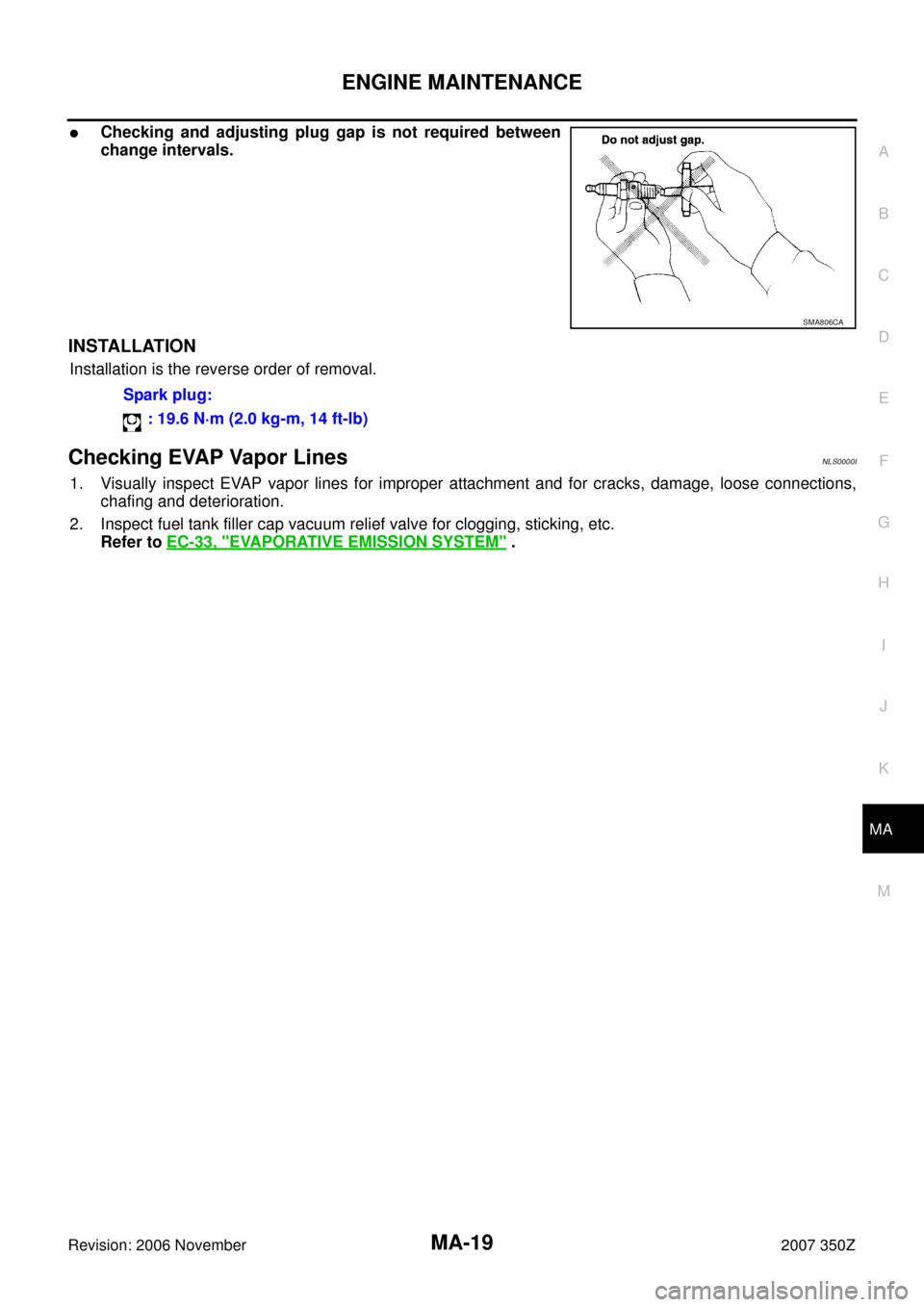
�Checking and adjusting plug gap is not required between
change intervals.
INSTALLATION
Installation is the reverse order of removal.
Checking EVAP Vapor LinesNLS0000I
1. Visually inspect EVAP vapor lines for improper attachment and for cracks, damage, loose connections,
chafing and deterioration.
2. Inspect fuel tank filler cap vacuum relief valve for clogging, sticking, etc.
Refer to EC-33, "
EVAPORATIVE EMISSION SYSTEM" .
SMA806CA
Spark plug:
: 19.6 N·m (2.0 kg-m, 14 ft-lb)
Page 20 of 30
MA-20
CHASSIS AND BODY MAINTENANCE
Revision: 2006 November2007 350Z
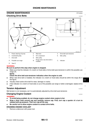
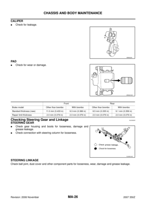
CHASSIS AND BODY MAINTENANCEPFP:00100
Checking Exhaust SystemNLS0000J
Check exhaust pipes, muffler and mounting for improper attachment,
leaks, cracks, damage, chafing or deterioration.
�If anything is found, repair or replace damaged parts.
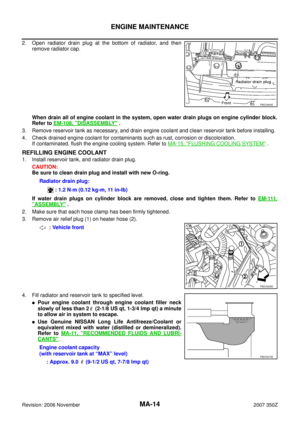
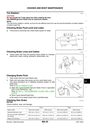
Checking Clutch Fluid Level and LeaksNLS0000K
If fluid level is extremely low, check clutch system for leaks.
Checking M/T OilNLS0000L
Check for oil leakage.
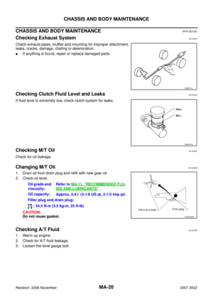
Changing M/T OilNLS0000M
1. Drain oil from drain plug and refill with new gear oil.
2. Check oil level.
CAUTION:
Do not reuse gasket.
Checking A/T FluidNLS0000N
1. Warm up engine.
2. Check for A/T fluid leakage.
3. Loosen the level gauge bolt.
SMA211A
SMA941B
Oil grade and
viscosity:Refer to MA-11, "RECOMMENDED FLU-
IDS AND LUBRICANTS" .
Oil capacity:
Approx. 2.9 (3-1/8 US qt, 2-1/2 lmp qt)
Filler plug and drain plug:
: 34.5 N·m (3.5 kg-m, 25 ft-lb)
PCIB0268E
Page 21 of 30

CHASSIS AND BODY MAINTENANCE
MA-21
C
D
E
F
G
H
I
J
K
MA
B
MA
Revision: 2006 November2007 350Z
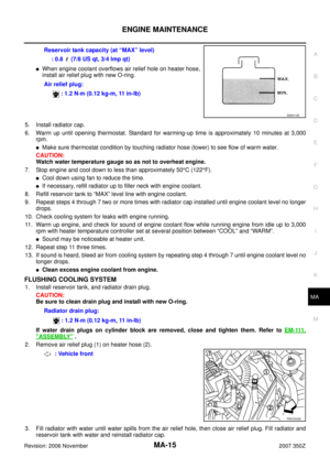
4. Before driving, A/T fluid level can be checked at A/T fluid tem-
peratures of 30 to 50°C (86 to 122°F) using “COLD” range on A/
T fluid level gauge as follows.
a. Park vehicle on level surface and set parking brake.
b. Start engine and move selector lever through each gear posi-
tion. Leave selector lever in “P” position.
c. Check A/T fluid level with engine idling.
d. Remove A/T fluid level gauge and wipe clean with lint-free
paper.
CAUTION:
When wiping away the A/T fluid level gauge, always use
lint-free paper, not a cloth one.
e. Re-insert A/T fluid level gauge into A/T fluid charging pipe as far as it will go.
CAUTION:
To check A/T fluid level, insert the A/T fluid level gauge until the cap contacts the end of the A/T
fluid charging pipe, with the A/T fluid level gauge reversed from the normal attachment conditions.
f. Remove A/T fluid level gauge and note reading. If reading is at low side of range, add ATF to the A/T fluid
charging pipe.
CAUTION:
Do not overfill.
5. Drive vehicle for approximately 5 minutes in urban areas.
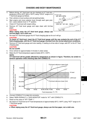
6. Make the A/T fluid temperature approximately 65°C (149°F).
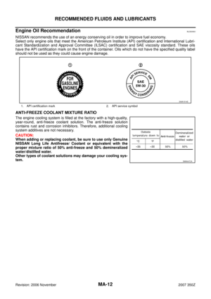
NOTE:
A/T fluid level will be greatly affected by temperature as shown in figure. Therefore, be certain to
perform operation while checking data with CONSULT-II.
a. Connect CONSULT-II to data link connector.
b. Select “MAIN SIGNALS” in “DATA MONITOR” mode for “A/T” with CONSULT-II.
c. Read out the value of “ATF TEMP 1”.
7. Re-check A/T fluid level at A/T fluid temperatures of approximately 65°C (149°F) using “HOT” range on A/
T fluid level gauge.
CAUTION:
�When wiping away the A/T fluid level gauge, always use lint-free paper, not a cloth one.
SCIA7120E
SLIA0016E
Page 22 of 30

MA-22
CHASSIS AND BODY MAINTENANCE
Revision: 2006 November2007 350Z
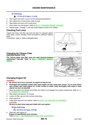
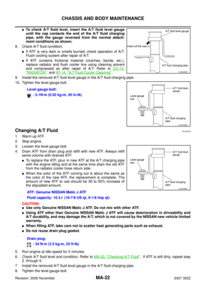
�To check A/T fluid level, insert the A/T fluid level gauge
until the cap contacts the end of the A/T fluid charging
pipe, with the gauge reversed from the normal attach-
ment conditions as shown.
8. Check A/T fluid condition.
�If ATF is very dark or smells burned, check operation of A/T.
Flush cooling system after repair of A/T.
�If ATF contains frictional material (clutches, bands, etc.),
replace radiator and flush cooler line using cleaning solvent
and compressed air after repair of A/T. Refer to CO-13,
"RADIATOR" and AT- 1 4 , "A/T Fluid Cooler Cleaning" .
9. Install the removed A/T fluid level gauge in the A/T fluid charging pipe.
10. Tighten the level gauge bolt.
Changing A/T FluidNLS0000O
1. Warm up ATF.
2. Stop engine.
3. Loosen the level gauge bolt.
4. Drain ATF from drain plug and refill with new ATF. Always refill
same volume with drained ATF.
�To replace the ATF, pour in new ATF at the A/T charging pipe
with the engine idling and at the same time drain the old ATF
from the radiator cooler hose return side.
�When the color of the ATF coming out is about the same as
the color of the new ATF, the replacement is complete. The
amount of new ATF to use should be 30 to 50% increase of
the stipulated amount.
CAUTION:
�Use only Genuine NISSAN Matic J ATF. Do not mix with other ATF.
�Using ATF other than Genuine NISSAN Matic J ATF will cause deterioration in driveability and
A/T durability, and may damage the A/T, which is not covered by the NISSAN new vehicle limited
warranty.
�When filling ATF, take care not to scatter heat generating parts such as exhaust.
�Do not reuse drain plug gasket.
5. Run engine at idle speed for 5 minutes.
6. Check A/T fluid level and condition. Refer to MA-20, "
Checking A/T Fluid" . If ATF is still dirty, repeat step
2. through 5.
7. Install the removed A/T fluid level gauge in the A/T fluid charging pipe.
8. Tighten the level gauge bolt.Level gauge bolt:
: 5.1N·m (0.52 kg-m, 45 in-lb)
SCIA2899E
SCIA4896E
ATF: Genuine NISSAN Matic J ATF
Fluid capacity: 10.3 (10-7/8 US qt, 9-1/8 lmp qt)
Drain plug:
: 34 N·m (3.5 kg-m, 25 ft-lb)
SCIA4896E
Page 23 of 30

CHASSIS AND BODY MAINTENANCE
MA-23
C
D
E
F
G
H
I
J
K
MA
B
MA
Revision: 2006 November2007 350Z
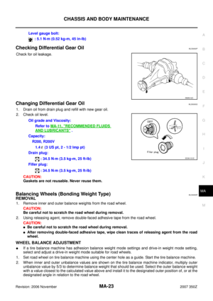
Checking Differential Gear OilNLS0000P
Check for oil leakage.
Changing Differential Gear OilNLS0000Q
1. Drain oil from drain plug and refill with new gear oil.
2. Check oil level.
CAUTION:
Gaskets are not reusable. Never reuse them.
Balancing Wheels (Bonding Weight Type)NLS0000R
REMOVAL
1. Remove inner and outer balance weights from the road wheel.
CAUTION:
Be careful not to scratch the road wheel during removal.
2. Using releasing agent, remove double-faced adhesive tape from the road wheel.
CAUTION:
�Be careful not to scratch the road wheel during removal.
�After removing double-faced adhesive tape, wipe clean traces of releasing agent from the road
wheel.
WHEEL BALANCE ADJUSTMENT
�If a tire balance machine has adhesion balance weight mode settings and drive-in weight mode setting,
select and adjust a drive-in weight mode suitable for road wheels.
1. Set road wheel on tire balance machine using the center hole as a guide. Start the tire balance machine.
2. When inner and outer unbalance values are shown on the tire balance machine indicator, multiply outer
unbalance value by 5/3 to determine balance weight that should be used. Select the outer balance weight
with a value closest to the calculated value above and install it to the designated outer position of, or at the
designated angle in relation to the road wheel.Level gauge bolt:
: 5.1 N·m (0.52 kg-m, 45 in-lb)
SMA012C
Oil grade and Viscosity:
Refer to MA-11, "
RECOMMENDED FLUIDS
AND LUBRICANTS" .
Capacity:
R200, R200V
1.4 (3 US pt, 2 - 1/2 lmp pt)
Drain plug:
: 34.5 N·m (3.5 kg-m, 25 ft-lb)
Filler plug:
: 34.5 N·m (3.5 kg-m, 25 ft-lb)
SDIA1151E
Page 24 of 30

MA-24
CHASSIS AND BODY MAINTENANCE
Revision: 2006 November2007 350Z
CAUTION:
�Do not install the inner balance weight before installing the outer balance weight.
�Before installing the balance weight, be sure to clean the
mating surface of the road wheel.
Indicated unbalance value × 5/3 = balance weight to be installed
Calculation example:
23 g (0.81 oz) × 5/3 = 38.33 g (1.35 oz) = 40 g (1.41 oz) balance
weight (closer to calculated balance weight value)
Note that balance weight value must be closer to the calculated
balance weight value.
Example:
37.4 = 35 g (1.23 oz)
37.5 = 40 g (1.41 oz)
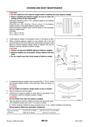
a. Install balance weight in the position shown in the figure at right.
b. When installing balance weight to road wheels, set it into the
grooved area on the inner wall of the road wheel as shown in the
figure so that the balance weight center is aligned with the tire
balance machine indication position (angle).
CAUTION:
�Always use genuine NISSAN adhesion balance weights.
�Balance weights are unreusable; always replace with new
ones.
�Do not install more than three sheets of balance weight.
c. If calculated balance weight value exceeds 50 g (1.76 oz), install
two balance weight sheets in line with each other (as shown in
the figure).
CAUTION:
Do not install one balance weight sheet on top of another.
3. Start tire balance machine again.
4. Install drive-in balance weight on inner side of road wheel in the
tire balance machine indication position (angle).
CAUTION:
Do not install more than two balance weights.
5. Start tire balance machine. Make sure that inner and outer resid-
ual unbalance values are 5 g (0.17 oz) each or below.
�If either residual unbalance value exceeds 5 g (0.17 oz), repeat installation procedures.
Wheel balance (Maximum allowable unbalance):
SMA054D
SEIA0166E
Maximum allowable
unbalanceDynamic (At rim flange) Less than 5 g (0.17 oz) (one side)
Static (At rim flange) Less than 10 g (0.35 oz)
SMA056D