Page 49 of 82

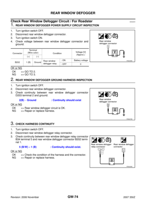
POWER WINDOW SYSTEM
GW-49
C
D
E
F
G
H
J
K
L
MA
B
GW
Revision: 2006 November2007 350Z
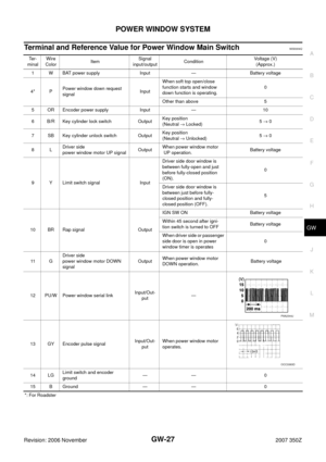
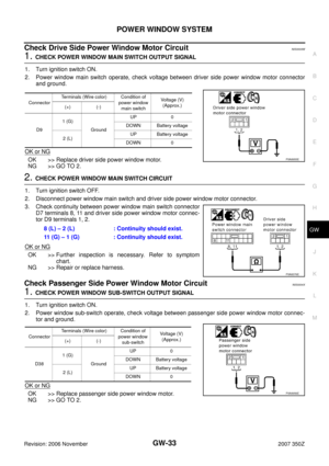
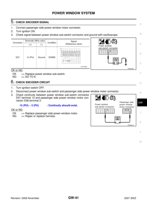
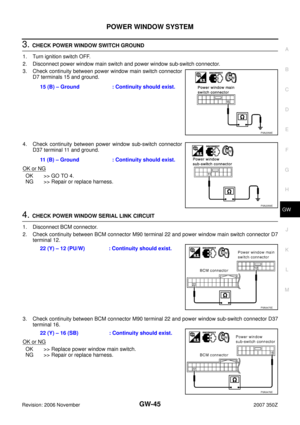
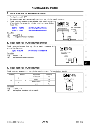
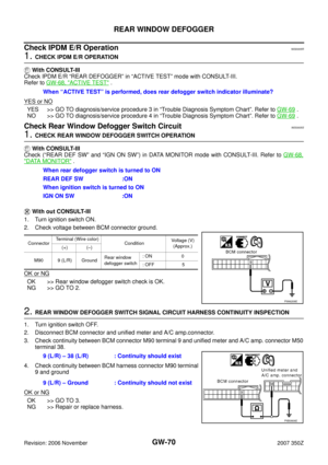
2. CHECK DOOR KEY CYLINDER SWITCH CIRCUIT
1. Turn ignition switch OFF.
2. Disconnect power window main switch and door key cylinder switch connector.
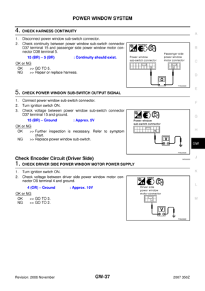
3. Check continuity between power window main switch connector
D7 terminal 6, 7 and door key cylinder switch connector D12 ter-
minals 1, 3.
OK or NG
OK >> GO TO 3.
NG >> Repair or replace harness.
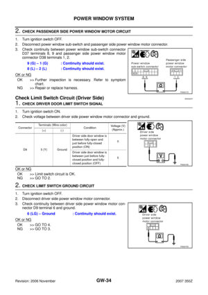
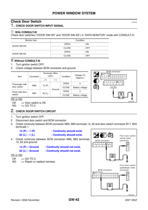
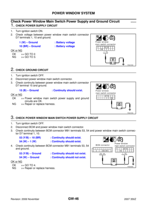
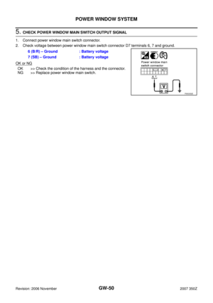
3. CHECK DOOR KEY CYLINDER SWITCH GROUND
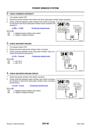
Check continuity between door key cylinder switch connector D12
terminal 2 and ground.
OK or NG
OK >> GO TO 4.
NG >> Repair or replace harness.
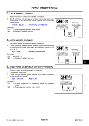
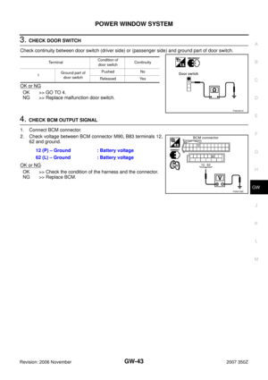
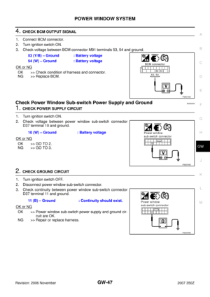
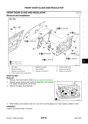
4. CHECK DOOR KEY CYLINDER SWITCH
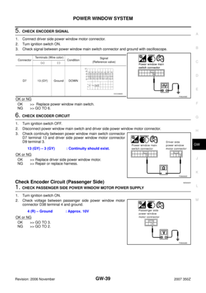
Check continuity between door key cylinder switch connector D12 terminals 1, 3 and 2.
OK or NG
OK >> GO TO 5.
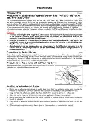
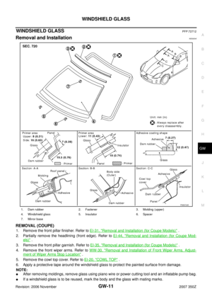
NG >> Replace door key cylinder switch.6 (B/R) – 3 (B/R) : Continuity should exist.
7 (SB) – 1 (SB) : Continuity should exist.
PIIA3353E
2 (B) – Ground : Continuity should exist.
PIIA3354E
Connector Terminal Key position Continuity
D121
2Neutral/Lock No
Unlock Yes
3Neutral/Unlock No
Lock Yes
PIIA3355E
Page 50 of 82
GW-50
POWER WINDOW SYSTEM
Revision: 2006 November2007 350Z
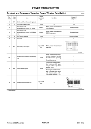
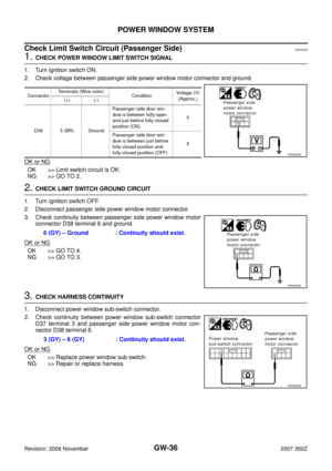
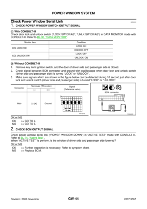
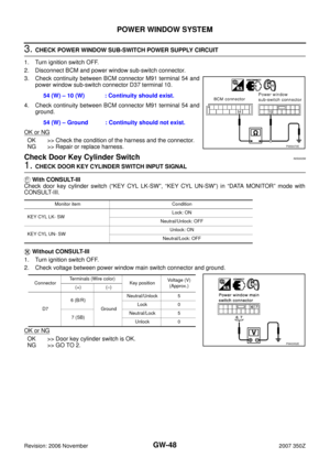
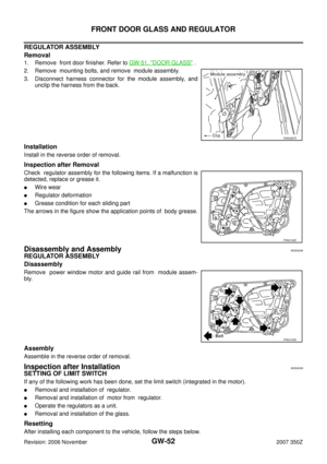
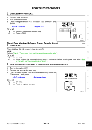
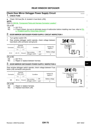
5. CHECK POWER WINDOW MAIN SWITCH OUTPUT SIGNAL
1. Connect power window main switch connector.
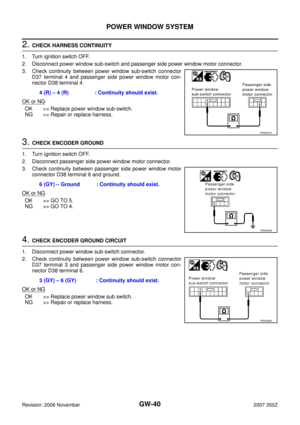
2. Check voltage between power window main switch connector D7 terminals 6, 7 and ground.
OK or NG
OK >> Check the condition of the harness and the connector.
NG >> Replace power window main switch.6 (B/R) – Ground : Battery voltage
7 (SB) – Ground : Battery voltage
PIIA3352E
Page 51 of 82
FRONT DOOR GLASS AND REGULATOR
GW-51
C
D
E
F
G
H
J
K
L
MA
B
GW
Revision: 2006 November2007 350Z
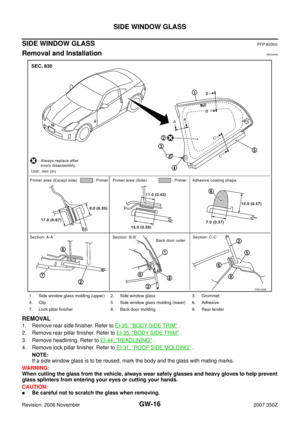
FRONT DOOR GLASS AND REGULATORPFP:80300
Removal and InstallationNIS00057
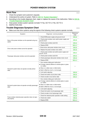
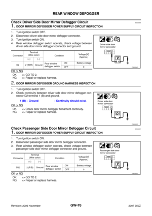
DOOR GLASS
Removal
1. Remove front door finisher. Refer to EI-33, "DOOR FINISHER" .
2. Operate power window main switch to raise/lower door window
until glass mounting bolts can be seen.
3. Remove the glass mounting bolts.
4. While holding door window, raise it at rear end to pull the glass out of sash toward outside of door.
Installation
Install in the reverse order of removal.
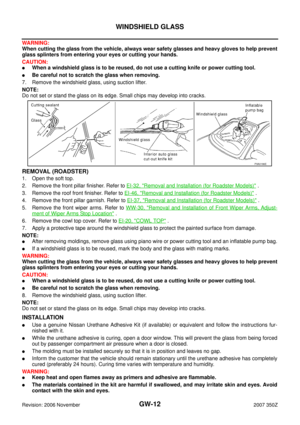
1. Door glass 2. Regulator assembly 3. Power window motor
4. Module assembly 5. Glass stabilizer 6. Glass mounting bolt
7. Regulator mounting bolt 8. Regulator mounting nut 9. Module mounting bolt
10. Power window motor mounting bolt
PIIB0823E
PIIA2161E
Page 52 of 82

GW-52
FRONT DOOR GLASS AND REGULATOR
Revision: 2006 November2007 350Z
REGULATOR ASSEMBLY
Removal
1. Remove front door finisher. Refer to GW-51, "DOOR GLASS" .
2. Remove mounting bolts, and remove module assembly.
3. Disconnect harness connector for the module assembly, and
unclip the harness from the back.
Installation
Install in the reverse order of removal.
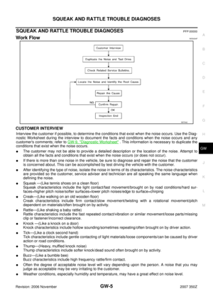
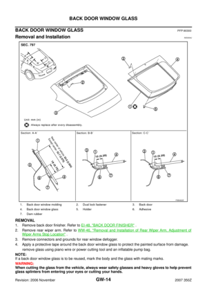
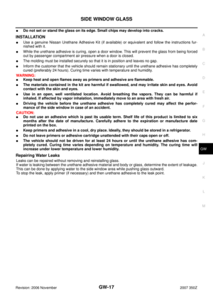
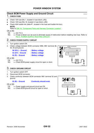
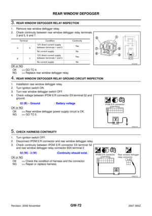
Inspection after Removal
Check regulator assembly for the following items. If a malfunction is
detected, replace or grease it.
�Wire wear
�Regulator deformation
�Grease condition for each sliding part
The arrows in the figure show the application points of body grease.
Disassembly and AssemblyNIS00058
REGULATOR ASSEMBLY
Disassembly
Remove power window motor and guide rail from module assem-
bly.
Assembly
Assemble in the reverse order of removal.
Inspection after InstallationNIS00059
SETTING OF LIMIT SWITCH
If any of the following work has been done, set the limit switch (integrated in the motor).
�Removal and installation of regulator.
�Removal and installation of motor from regulator.
�Operate the regulators as a unit.
�Removal and installation of the glass.
Resetting
After installing each component to the vehicle, follow the steps below.
SIIA0287E
PIIA2162E
PIIA2163E
Page 53 of 82

FRONT DOOR GLASS AND REGULATOR
GW-53
C
D
E
F
G
H
J
K
L
MA
B
GW
Revision: 2006 November2007 350Z
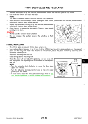
1. With the door open, lift up and hold the power window switch until the door glass is fully closed.
2. Get inside the vehicle and close the door.
NOTE:
You need to close the door so the door switch is fully depressed.
3. Press and hold the reset switch. While holding the reset switch, press down and hold the power window
switch until the door glass is fully opened.
4. Relese the reset switch.Then, lift up and hold the power window
switch until the door glass is fully closed.
5. Open the door to release the door switch. The door glass should
partially move down.
CAUTION:
�Do not use the window auto function.
�Do not release the switch before the window is fully
stopped.
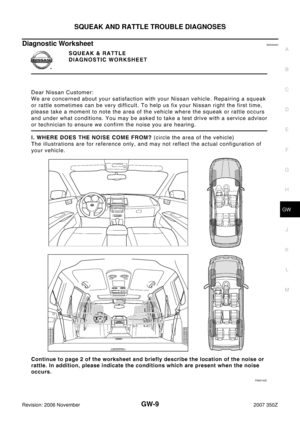
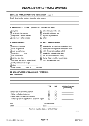
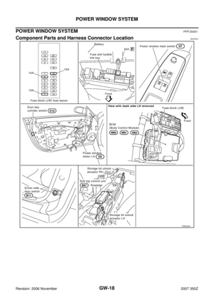
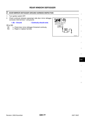
FITTING INSPECTION
�Check that glass is securely fit into glass run groove.
�Lower glass slightly [approx. 10 to 20 mm (0.39 to 0.79 in)] and check the distance between the edge of
glass and the body side welt. If the distance is not constant, adjust the glass position by loosening and
tightening following bolts.
–Regulator mounting bolt and nut
–Glass and guide rail mounting bolt
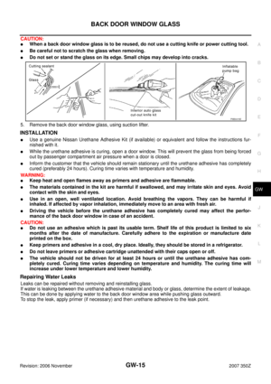
�Raise the glass fully and adjust the glass top end and body side
welt fitting with the adjusting bolt at the lower of the regulator
rear rail.
NOTE:
�Turn the adjusting bolt clockwise to move the door glass
upper end outward.
�Turn the adjusting bolt counterclockwise to move the door
glass upper end inward.
�If water leaks, repair the fitting (Roadster only). Refer to RF-
11 6 , "Repairing Method for Water Leakage Around Doors" .
SIIA0347E
PIIA7672E
Page 54 of 82
GW-54
INSIDE MIRROR
Revision: 2006 November2007 350Z
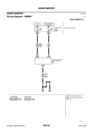
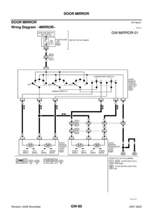
INSIDE MIRRORPFP:96321
Wiring Diagram –I/MIRR–NIS0005A
TIWT2276E
Page 55 of 82
INSIDE MIRROR
GW-55
C
D
E
F
G
H
J
K
L
MA
B
GW
Revision: 2006 November2007 350Z
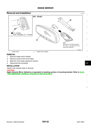
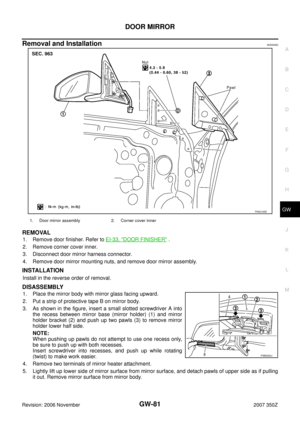
Removal and InstallationNIS0005B
REMOVAL
1. Remove inside mirror finisher.
2. Remove screw of the mirror base.
3. Slide the mirror base upward to remove.
4. Disconnect the connector.
INSTALLATION
Install in the reverse order of removal.
CAUTION:
Apply Genuine Mirror Adhesive or equivalent to bonding surface of mounting bracket. Refer to GI-45,
"RECOMMENDED CHEMICAL PRODUCTS AND SEALANTS" .
1. Inside mirror 2. Inside mirror finisher
PIIA9845E
Page 56 of 82

GW-56
REAR WINDOW DEFOGGER
Revision: 2006 November2007 350Z
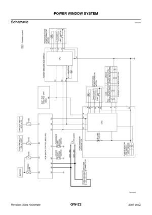
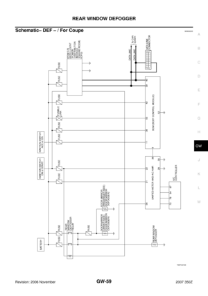
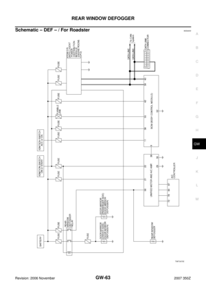
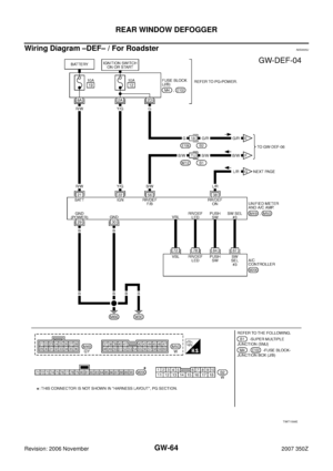
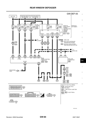
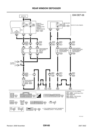
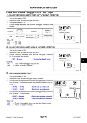
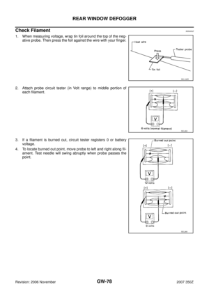
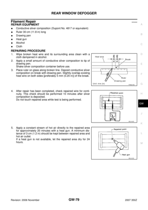
REAR WINDOW DEFOGGERPFP:25350
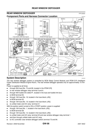
Component Parts and Harness Connector LocationNIS0005C
System DescriptionNIS0005D
The rear window defogger system is controlled by BCM (Body Control Module) and IPDM E/R (Intelligent
Power Distribution Module Engine Room). The rear window defogger operates only for approximately 15 min-
utes.
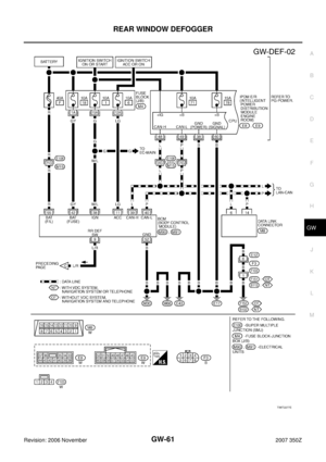
Power is supplied at all times
�through 20A fuse [No. 75 and 80, located in the IPDM E/R]
�to rear window defogger relay terminal 3 and 6.
�through 40A fusible link (letter F , located in the fuse and fusible link box)
�to BCM terminal 55.
�through 10A fuse [No. 18, located in the fuse block (J/B)]
�to BCM terminal 42.
�through 10A fuse [No. 19, located in the fuse block (J/B)]
�to unified meter and A/C amp. terminal 21.
With the ignition switch turned to ON or START position, power is supplied
�through 10A fuse [No. 1, located in the fuse block (J/B)]
�to BCM terminal 38.
�through 10A fuse [No. 12, located in the fuse block (J/B)]
�to unified meter and A/C amp. terminal 22 and rear window defogger relay terminal 1
�and then through unified meter and A/C amp.
�to A/C controller (rear window defogger switch) terminal 72 and 84.
PIIB3830E