Page 16 of 148
EM-16
AIR CLEANER AND AIR DUCT
Revision: 2006 November2007 350Z
3. Disconnect PCV hose.
4. Remove air cleaner case/mass air flow sensor assembly and air duct assembly disconnecting their joints.
�Add marks as necessary for easier installation.
5. Remove mass air flow sensor from air cleaner case.
CAUTION:
Handle mass air flow sensor with care.
�Do not shock it.
�Do not disassemble it.
�Do not touch its sensor.
INSPECTION AFTER REMOVAL
Inspect air duct for crack or tear.
�If anything found, replace air duct.
INSTALLATION
Note the following, and install in the reverse order of removal.
�Align marks. Attach each joint. Screw clamps firmly.
CAUTION:
Keep the clearance more than 5 mm between tower bar and air duct.
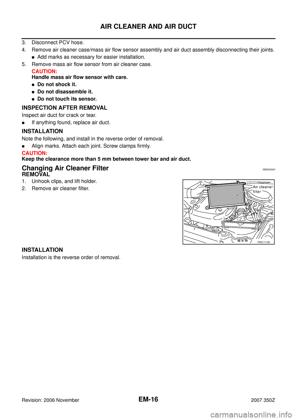
Changing Air Cleaner FilterNBS0000H
REMOVAL
1. Unhook clips, and lift holder.
2. Remove air cleaner filter.
INSTALLATION
Installation is the reverse order of removal.
PBIC1118E
Page 17 of 148
INTAKE MANIFOLD COLLECTOR
EM-17
C
D
E
F
G
H
I
J
K
L
MA
EM
Revision: 2006 November2007 350Z
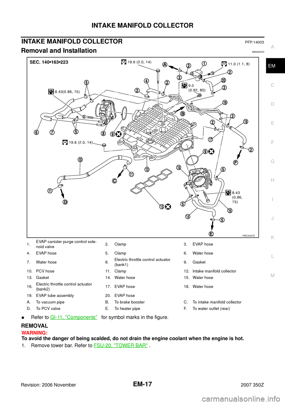
INTAKE MANIFOLD COLLECTORPFP:14003
Removal and InstallationNBS006VD
�Refer to GI-11, "Components" for symbol marks in the figure.
REMOVAL
WARNING:
To avoid the danger of being scalded, do not drain the engine coolant when the engine is hot.
1. Remove tower bar. Refer to FSU-20, "
TOWER BAR" .
1.EVAP canister purge control sole-
noid valve2. Clamp 3. EVAP hose
4. EVAP hose 5. Clamp 6. Water hose
7. Water hose 8.Electric throttle control actuator
(bank1)9. Gasket
10. PCV hose 11. Clamp 12. Intake manifold collector
13. Gasket 14. Water hose 15. Water hose
16.Electric throttle control actuator
(bank2)17. EVAP hose 18. Water hose
19. EVAP tube assembly 20. EVAP hose
A. To vacuum pipe B. To brake booster C. To intake manifold collector
D. To PCV valve E. To heater pipe F. To water outlet (rear)
PBIC4947E
Page 22 of 148

EM-22
EXHAUST MANIFOLD AND THREE WAY CATALYST
Revision: 2006 November2007 350Z
EXHAUST MANIFOLD AND THREE WAY CATALYSTPFP:14004
Removal and InstallationNBS0000K
�Refer to GI-11, "Components" for symbol marks in the figure.
REMOVAL
WARNING:
Perform the work when the exhaust and cooling system have completely cooled down.
NOTE:
When removing right bank side parts only, step 3, 10 and 11 are unnecessary.
1. Remove tower bar. Refer to FSU-20, "
TOWER BAR" .
2. Remove engine cover with power tool. Refer to EM-17, "
INTAKE MANIFOLD COLLECTOR" .
3. Drain engine coolant. Refer to CO-10, "
Changing Engine Coolant" .
CAUTION:
�Perform this step when engine is cold.
�Do not spill engine coolant on drive belts.
4. Remove air cleaner case and air duct. Refer to EM-15, "
AIR CLEANER AND AIR DUCT" .
1. Heated oxygen sensor (bank 1) 2. Air fuel ratio sensor (bank 1) 3.Exhaust manifold cover
(upper)
4. Exhaust manifold (right bank) 5. Exhaust manifold cover (lower) 6. Gasket
7. Ring gasket 8. Three way catalyst (right bank) 9. Gasket
10. Heated oxygen sensor (bank 2) 11. Gasket 12. Three way catalyst (left bank)
13. Ring gasket 14. Exhaust manifold (left bank) 15. Exhaust manifold cover (lower)
16. Gasket 17. Air fuel ratio sensor (bank 2) 18.Exhaust manifold cover
(upper)
PBIC4952E
Page 102 of 148

EM-102
ENGINE ASSEMBLY
Revision: 2006 November2007 350Z
REMOVAL
Outline
At first, remove engine and transmission assembly with front suspension member from vehicle downward.
Then separate engine from transmission.
Preparation
1. Release fuel pressure. Refer to EC-79, "FUEL PRESSURE RELEASE" .
2. Drain engine coolant from radiator. Refer to CO-10, "
Changing Engine Coolant" .
CAUTION:
�Perform this step when engine is cold.
�Do not spill engine coolant on drive belts.
3. Disconnect both battery cables. Refer to SC-4, "
BATTERY" .
4. Remove the following parts:
�Tower bar: Refer to FSU-20, "TOWER BAR" .
�Engine cover: Refer to EM-17, "INTAKE MANIFOLD COLLECTOR" .
�Cowl top cover (RH): Refer to EI-20, "COWL TOP" .
�Undercover
�Drive belts: Refer to EM-12, "DRIVE BELTS" .
�Front road wheels and tires
5. Remove air cleaner case and air duct. Refer to EM-15, "
AIR CLEANER AND AIR DUCT" .
6. Discharge refrigerant from A/C circuit. Refer to ATC-123, "
REFRIGERANT LINES" .
7. Remove radiator cooling fan assembly, reservoir tank and hoses. Refer to CO-21, "
COOLING FAN" and
CO-13, "
RADIATOR" .
Engine Room
1. Disconnect heater hose at engine-side, and fit a plug onto hose end to prevent engine coolant leak.
2. Disconnect ground cable (between vehicle to left cylinder head).
3. Disconnect battery positive cable harness at vehicle side and temporarily fasten it on engine.
4. Disconnect A/C piping from A/C compressor, and temporarily fasten it on vehicle with a rope.
5. Remove engine room harness connectors as shown in the fig-
ure.
6. Disconnect two body ground cables.
7. Disconnect brake booster vacuum hose.
8. Disconnect fuel feed hose (with damper) and EVAP hose. Refer to EM-34, "
FUEL INJECTOR AND FUEL
TUBE" .
CAUTION:
Fit plugs onto disconnected hoses to prevent fuel leak.
9. Remove reservoir tank of power steering oil pump, and piping from vehicle, and temporarily secure them
on engine.
CAUTION:
When temporarily securing, keep the reservoir tank upright to avoid a fluid leak.
Passenger Room Side
Follow procedure below to disconnect engine room harness connectors at passenger room side, and tempo-
rarily secure them on engine.
PBIC1105E