FUEL INJECTOR AND FUEL TUBE
EM-37
C
D
E
F
G
H
I
J
K
L
MA
EM
Revision: 2006 November2007 350Z
INSTALLATION
1. Install fuel damper as follows:
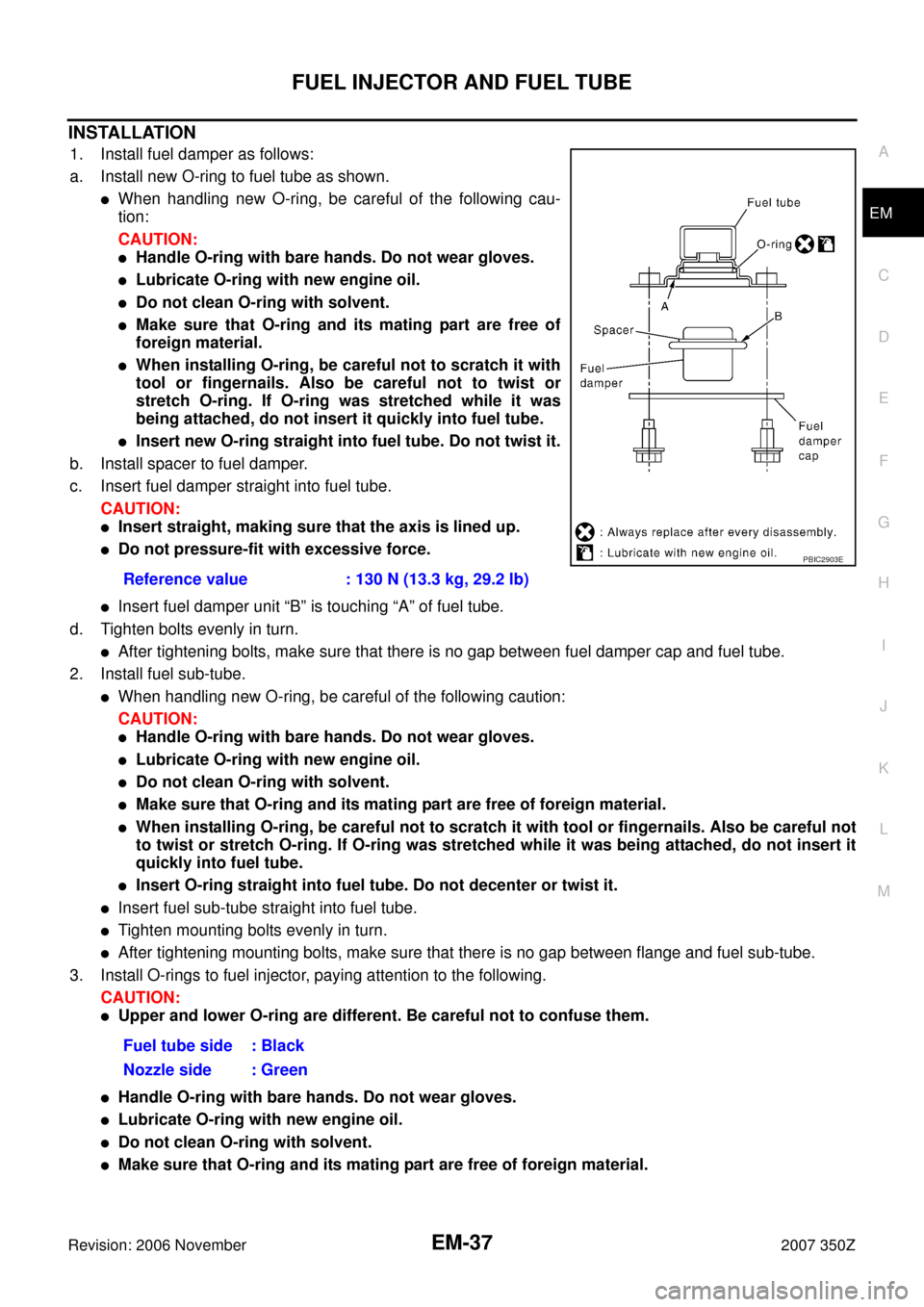
a. Install new O-ring to fuel tube as shown.
�When handling new O-ring, be careful of the following cau-
tion:
CAUTION:
�Handle O-ring with bare hands. Do not wear gloves.
�Lubricate O-ring with new engine oil.
�Do not clean O-ring with solvent.
�Make sure that O-ring and its mating part are free of
foreign material.
�When installing O-ring, be careful not to scratch it with
tool or fingernails. Also be careful not to twist or
stretch O-ring. If O-ring was stretched while it was
being attached, do not insert it quickly into fuel tube.
�Insert new O-ring straight into fuel tube. Do not twist it.
b. Install spacer to fuel damper.
c. Insert fuel damper straight into fuel tube.
CAUTION:
�Insert straight, making sure that the axis is lined up.
�Do not pressure-fit with excessive force.
�Insert fuel damper unit “B” is touching “A” of fuel tube.
d. Tighten bolts evenly in turn.
�After tightening bolts, make sure that there is no gap between fuel damper cap and fuel tube.
2. Install fuel sub-tube.
�When handling new O-ring, be careful of the following caution:
CAUTION:
�Handle O-ring with bare hands. Do not wear gloves.
�Lubricate O-ring with new engine oil.
�Do not clean O-ring with solvent.
�Make sure that O-ring and its mating part are free of foreign material.
�When installing O-ring, be careful not to scratch it with tool or fingernails. Also be careful not
to twist or stretch O-ring. If O-ring was stretched while it was being attached, do not insert it
quickly into fuel tube.
�Insert O-ring straight into fuel tube. Do not decenter or twist it.
�Insert fuel sub-tube straight into fuel tube.
�Tighten mounting bolts evenly in turn.
�After tightening mounting bolts, make sure that there is no gap between flange and fuel sub-tube.
3. Install O-rings to fuel injector, paying attention to the following.
CAUTION:
�Upper and lower O-ring are different. Be careful not to confuse them.
�Handle O-ring with bare hands. Do not wear gloves.
�Lubricate O-ring with new engine oil.
�Do not clean O-ring with solvent.
�Make sure that O-ring and its mating part are free of foreign material.Reference value : 130 N (13.3 kg, 29.2 lb)
Fuel tube side : Black
Nozzle side : Green
PBIC2903E
CYLINDER HEAD
EM-89
C
D
E
F
G
H
I
J
K
L
MA
EM
Revision: 2006 November2007 350Z
CYLINDER HEADPFP:11041
On-Vehicle ServiceNBS0000Y
CHECKING COMPRESSION PRESSURE
1. Warm up engine thoroughly. Then, stop it.
2. Release fuel pressure. Refer to EC-79, "
FUEL PRESSURE RELEASE" .
3. Disconnect fuel pump fuse to avoid fuel injection during mea-
surement.
4. Remove engine cover with power tool. Refer to EM-17, "
INTAKE MANIFOLD COLLECTOR" .
5. Remove ignition coil and spark plug from each cylinder. Refer to EM-31, "
IGNITION COIL" and EM-32,
"SPARK PLUG (IRIDIUM-TIPPED TYPE)" .
6. Connect engine tachometer (not required in use of CONSULT-III).
7. Install compression tester (Commercial service tool) with
adapter onto spark plug hole.
�Use the adapter whose picking up end inserted to spark plug
hole is smaller than 20 mm (0.79 in) in diameter. Otherwise, it
may be caught by cylinder head during removal.
8. With accelerator pedal fully depressed, turn ignition switch to “START” for cranking. When the gauge
pointer stabilizes, read the compression pressure and engine rpm. Perform these steps to check each cyl-
inder.
Compression pressure:
Unit: kPa (kg/cm2 , psi) /rpm
CAUTION:
Always use a fully changed battery to obtain specified engine speed.
PBIC2058E
PBIC0900E
SBIA0533E
Standard Minimum Differential limit between cylinders
1,275 (13.0, 185)/300 981 (10.0, 142)/300 98 (1.0, 14)/300