Page 85 of 148
CAMSHAFT
EM-85
C
D
E
F
G
H
I
J
K
L
MA
EM
Revision: 2006 November2007 350Z
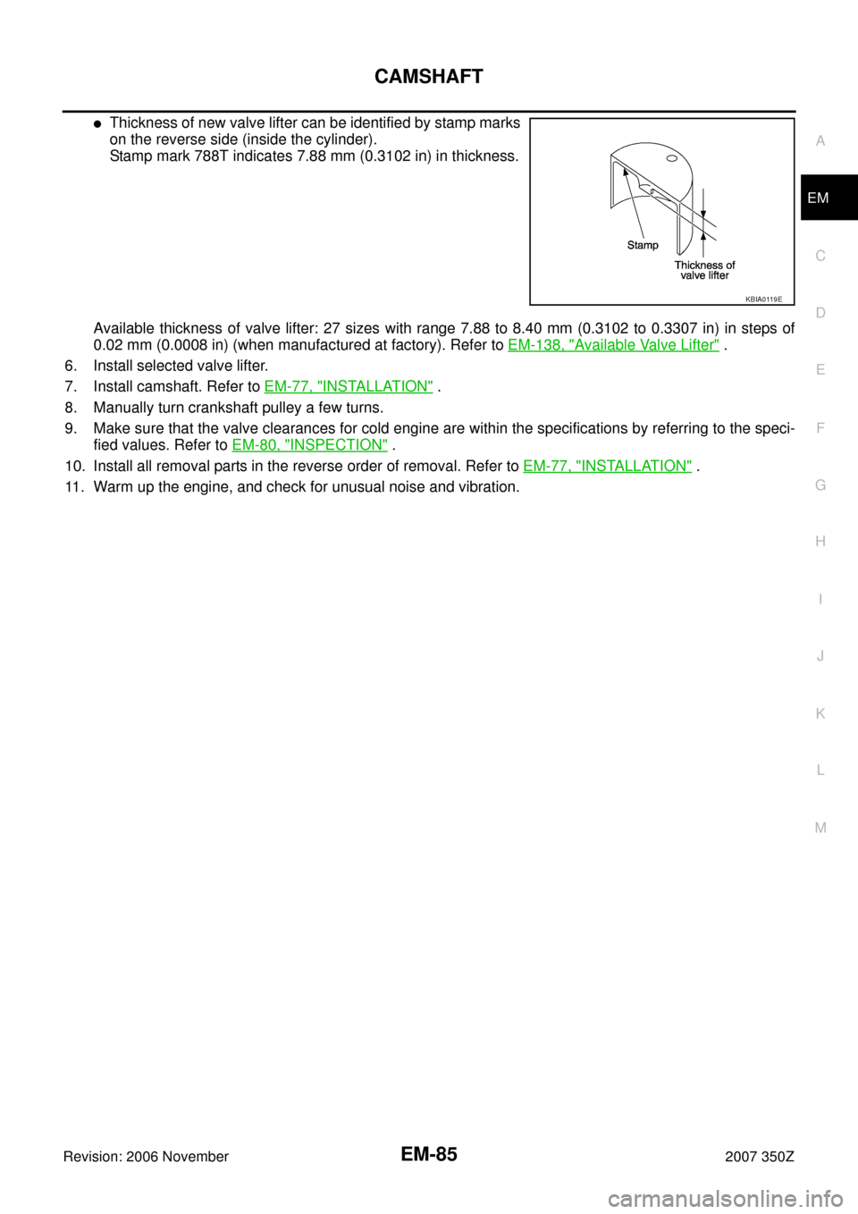
�Thickness of new valve lifter can be identified by stamp marks
on the reverse side (inside the cylinder).
Stamp mark 788T indicates 7.88 mm (0.3102 in) in thickness.
Available thickness of valve lifter: 27 sizes with range 7.88 to 8.40 mm (0.3102 to 0.3307 in) in steps of
0.02 mm (0.0008 in) (when manufactured at factory). Refer to EM-138, "
Available Valve Lifter" .
6. Install selected valve lifter.
7. Install camshaft. Refer to EM-77, "
INSTALLATION" .
8. Manually turn crankshaft pulley a few turns.
9. Make sure that the valve clearances for cold engine are within the specifications by referring to the speci-
fied values. Refer to EM-80, "
INSPECTION" .
10. Install all removal parts in the reverse order of removal. Refer to EM-77, "
INSTALLATION" .
11. Warm up the engine, and check for unusual noise and vibration.
KBIA0119E
Page 86 of 148

EM-86
OIL SEAL
Revision: 2006 November2007 350Z
OIL SEALPFP:00100
Removal and Installation of Valve Oil SealNBS0000V
REMOVAL
1. Remove camshaft relating to valve oil seal to be removed. Refer to EM-72, "CAMSHAFT" .
2. Remove valve lifters. Refer to EM-72, "
CAMSHAFT" .
3. Turn crankshaft until the cylinder requiring new oil seals is at TDC. This will prevent valve from dropping
into cylinder.
4. Remove valve collet.
�Compress valve spring with valve spring compressor, attach-
ment, adapter (SST). Remove valve collet with magnet hand.
CAUTION:
When working, take care not to damage valve lifter holes.
5. Remove valve spring retainer, valve spring and valve spring seat.
6. Remove valve oil seal using valve oil seal puller (SST).
INSTALLATION
1. Apply engine oil on new valve oil seal joint and seal lip.
2. Using valve oil seal drift (SST), press fit valve oil seal to height
“H” shown in the figure.
NOTE:
Dimension “H”: Height measured before valve spring seat instal-
lation
3. Install in the reverse order of removal after this step.
PBIC1803E
PBIC0884E
Intake and exhaust : 14.3 - 14.9 mm (0.563 - 0.587 in)
PBIC0802E
Page 87 of 148

OIL SEAL
EM-87
C
D
E
F
G
H
I
J
K
L
MA
EM
Revision: 2006 November2007 350Z
Removal and Installation of Front Oil SealNBS0000W
REMOVAL
1. Remove the following parts:
�Undercover
�Drive belts: Refer to EM-12, "DRIVE BELTS" .
�Radiator cooling fan assembly: Refer to CO-21, "COOLING FAN" .
�Crankshaft pulley: Refer to EM-53, "TIMING CHAIN" .
2. Remove front oil seal using suitable tool.
CAUTION:
Be careful not to damage front timing chain case and crank-
shaft.
INSTALLATION
1. Apply engine oil to both oil seal lip and dust seal lip of new front oil seal.
2. Install front oil seal.
�Install front oil seal so that each seal lip is oriented as shown
in the figure.
�Using suitable drift, press-fit until the height of front oil seal is
level with the mounting surface.
–Suitable drift: outer diameter 60 mm (2.36 in), inner diameter
50 mm (1.97 in).
CAUTION:
�Be careful not to damage front timing chain case and
crankshaft.
�Press-fit straight and avoid causing burrs or tilting oil
seal.
3. Install in the reverse order of removal after this step.
Removal and Installation of Rear Oil SealNBS0000X
REMOVAL
1. Remove transmission assembly. Refer to MT-18, "TRANSMISSION ASSEMBLY" (M/T models) or AT-
242, "TRANSMISSION ASSEMBLY" (A/T models).
2. Remove clutch cover and clutch disk (M/T models). Refer to CL-16, "
CLUTCH DISC, CLUTCH COVER" .
3. Remove flywheel (M/T models) or drive plate (A/T models). Refer to EM-107, "
CYLINDER BLOCK" .
PBIC2931E
SEM715A
PBIC2931E
Page 88 of 148
EM-88
OIL SEAL
Revision: 2006 November2007 350Z
4. Remove rear oil seal with a suitable tool.
CAUTION:
Be careful not to damage crankshaft and cylinder block.
INSTALLATION
1. Apply new engine oil to new rear oil seal joint surface and seal lip.
2. Install rear oil seal so that each seal lip is oriented as shown.
�Press in rear oil seal to the position as shown.
�Using suitable drift, press-fit until the height of front oil seal is
level with the mounting surface.
–Suitable drift: outer diameter 100 mm (3.94 in), inner diameter
85 mm (3.35 in).
CAUTION:
�Be careful not to damage crankshaft and cylinder block.
�Press-fit oil seal straight to avoid causing burrs or tilting.
3. Install in the reverse order of removal after this step.
PBIC2932E
SEM715A
SBIA0281E
LBIA0454E
Page 89 of 148

CYLINDER HEAD
EM-89
C
D
E
F
G
H
I
J
K
L
MA
EM
Revision: 2006 November2007 350Z
CYLINDER HEADPFP:11041
On-Vehicle ServiceNBS0000Y
CHECKING COMPRESSION PRESSURE
1. Warm up engine thoroughly. Then, stop it.
2. Release fuel pressure. Refer to EC-79, "
FUEL PRESSURE RELEASE" .
3. Disconnect fuel pump fuse to avoid fuel injection during mea-
surement.
4. Remove engine cover with power tool. Refer to EM-17, "
INTAKE MANIFOLD COLLECTOR" .
5. Remove ignition coil and spark plug from each cylinder. Refer to EM-31, "
IGNITION COIL" and EM-32,
"SPARK PLUG (IRIDIUM-TIPPED TYPE)" .
6. Connect engine tachometer (not required in use of CONSULT-III).
7. Install compression tester (Commercial service tool) with
adapter onto spark plug hole.
�Use the adapter whose picking up end inserted to spark plug
hole is smaller than 20 mm (0.79 in) in diameter. Otherwise, it
may be caught by cylinder head during removal.
8. With accelerator pedal fully depressed, turn ignition switch to “START” for cranking. When the gauge
pointer stabilizes, read the compression pressure and engine rpm. Perform these steps to check each cyl-
inder.
Compression pressure:
Unit: kPa (kg/cm2 , psi) /rpm
CAUTION:
Always use a fully changed battery to obtain specified engine speed.
PBIC2058E
PBIC0900E
SBIA0533E
Standard Minimum Differential limit between cylinders
1,275 (13.0, 185)/300 981 (10.0, 142)/300 98 (1.0, 14)/300
Page 90 of 148

EM-90
CYLINDER HEAD
Revision: 2006 November2007 350Z
�If the engine speed is out of specified range, check battery liquid for proper gravity. Check engine
speed again with normal battery gravity.
�If compression pressure is below minimum value, check valve clearances and parts associated with
combustion chamber (valve, valve seat, piston, piston ring, cylinder bore, cylinder head, cylinder head
gasket). After the checking, measure compression pressure again.
�If some cylinders have low compression pressure, pour small amount of engine oil into the spark plug
hole of the cylinder to re-check it for compression.
–If the added engine oil improves the compression, piston rings may be worn out or damaged. Check the
piston rings and replace if necessary.
–If the compression pressure remains at low level despite the addition of engine oil, valves may be mal-
functioning. Check valves for damage. Replace valve or valve seat accordingly.
�If two adjacent cylinders have respectively low compression pressure and their compression remains
low even after the addition of engine oil, cylinder head gaskets are leaking. In such a case, replace cyl-
inder head gaskets.
9. After inspection is completed, install removed parts.
10. Start engine, and make sure that engine runs smoothly.
11. Perform trouble diagnosis. If DTC appears, erase it. Refer to EC-81, "
TROUBLE DIAGNOSIS" .
Removal and InstallationNBS0000Z
�Refer to GI-11, "Components" for symbol marks in the figure.
REMOVAL
1. Remove engine assembly from vehicle, and separate front suspension member and transmission from
engine. Refer to EM-101, "
ENGINE ASSEMBLY" .
2. Remove the following parts:
1. Engine rear lower slinger 2. Cylinder head (left bank) 3. Cylinder head bolt
4. Cylinder head (right bank) 5. Cylinder head gasket (right bank) 6. Cylinder head gasket (left bank)
7. Oil level gauge guide
A. Refer to EM-92
PBIC4985E
Page 91 of 148

CYLINDER HEAD
EM-91
C
D
E
F
G
H
I
J
K
L
MA
EM
Revision: 2006 November2007 350Z
�Fuel tube and fuel injector assembly: Refer to EM-34, "FUEL INJECTOR AND FUEL TUBE" .
�Intake manifold: Refer to EM-20, "INTAKE MANIFOLD" .
�Exhaust manifold: Refer to EM-22, "EXHAUST MANIFOLD AND THREE WAY CATALYST" .
�Water inlet and thermostat assembly: Refer to CO-26, "WATER INLET AND THERMOSTAT ASSEM-
BLY" .
�Water outlet and water pipe: Refer to CO-28, "WATER OUTLET AND WATER PIPING" .
�Front and rear timing chain case: Refer to EM-53, "TIMING CHAIN" .
3. Remove camshaft (INT, EXH). Refer to EM-72, "
CAMSHAFT" .
4. Remove cylinder head bolts in reverse order as shown in the fig-
ure with cylinder head bolt wrench (commercial service tool).
5. Remove cylinder head gaskets.
INSPECTION AFTER REMOVAL
Cylinder Head Bolts Outer Diameter
�Cylinder head bolts are tightened by plastic zone tightening
method. Whenever the size difference between “d1” and “d2”
exceeds the limit, replace them with new one.
�If reduction of outer diameter appears in a position other than
“d2”, use it as “d2” point.
Cylinder Head Distortion
NOTE:
When performing this inspection, cylinder block distortion should be also checked. Refer to EM-128, "
CYLIN-
DER BLOCK DISTORTION" .
1. Using scraper, wipe off oil, scale, gasket, sealant and carbon deposits from surface of cylinder head.
CAUTION:
Do not allow gasket fragments to enter engine oil or engine coolant passages.
PBIC2057E
Limit (“d1” – “d2”) : 0.18 mm (0.0071 in)
PBIC2480E
Page 92 of 148

EM-92
CYLINDER HEAD
Revision: 2006 November2007 350Z
2. At each of several locations on bottom surface of cylinder head,
measure the distortion in six directions.
�If it exceeds the limit, replace cylinder head.
INSTALLATION
1. Install new cylinder head gaskets.
2. Turn crankshaft until No. 1 piston is set at TDC.
�Crankshaft key should line up with the right bank cylinder cen-
ter line as shown in the figure.
3. Install cylinder head follow the steps below to tighten cylinder
head bolts in numerical order as shown in the figure.
CAUTION:
If cylinder head bolts re-used, check their outer diameters
before installation. Refer to EM-91, "
Cylinder Head Bolts
Outer Diameter" .
a. Apply new engine oil to threads and seat surfaces of cylinder
head bolts.
b. Tighten all cylinder head bolts.
c. Completely loosen all cylinder head bolts.
CAUTION:
In step “c”, loosen bolts in reverse order of that indicated in
the figure.
d. Tighten all cylinder head bolts.Limit : 0.1 mm (0.004 in)
SEM861E
1 : Crankshaft key
: Right bank side
PBIC5012E
: 105 N·m (11 kg-m, 77 ft-lb)
: 0 N·m (0 kg-m, 0 ft-lb)
: 39.2 N·m (4.0 kg-m, 29 ft-lb)
PBIC2057E