Page 90 of 148

EM-90
CYLINDER HEAD
Revision: 2006 November2007 350Z
�If the engine speed is out of specified range, check battery liquid for proper gravity. Check engine
speed again with normal battery gravity.
�If compression pressure is below minimum value, check valve clearances and parts associated with
combustion chamber (valve, valve seat, piston, piston ring, cylinder bore, cylinder head, cylinder head
gasket). After the checking, measure compression pressure again.
�If some cylinders have low compression pressure, pour small amount of engine oil into the spark plug
hole of the cylinder to re-check it for compression.
–If the added engine oil improves the compression, piston rings may be worn out or damaged. Check the
piston rings and replace if necessary.
–If the compression pressure remains at low level despite the addition of engine oil, valves may be mal-
functioning. Check valves for damage. Replace valve or valve seat accordingly.
�If two adjacent cylinders have respectively low compression pressure and their compression remains
low even after the addition of engine oil, cylinder head gaskets are leaking. In such a case, replace cyl-
inder head gaskets.
9. After inspection is completed, install removed parts.
10. Start engine, and make sure that engine runs smoothly.
11. Perform trouble diagnosis. If DTC appears, erase it. Refer to EC-81, "
TROUBLE DIAGNOSIS" .
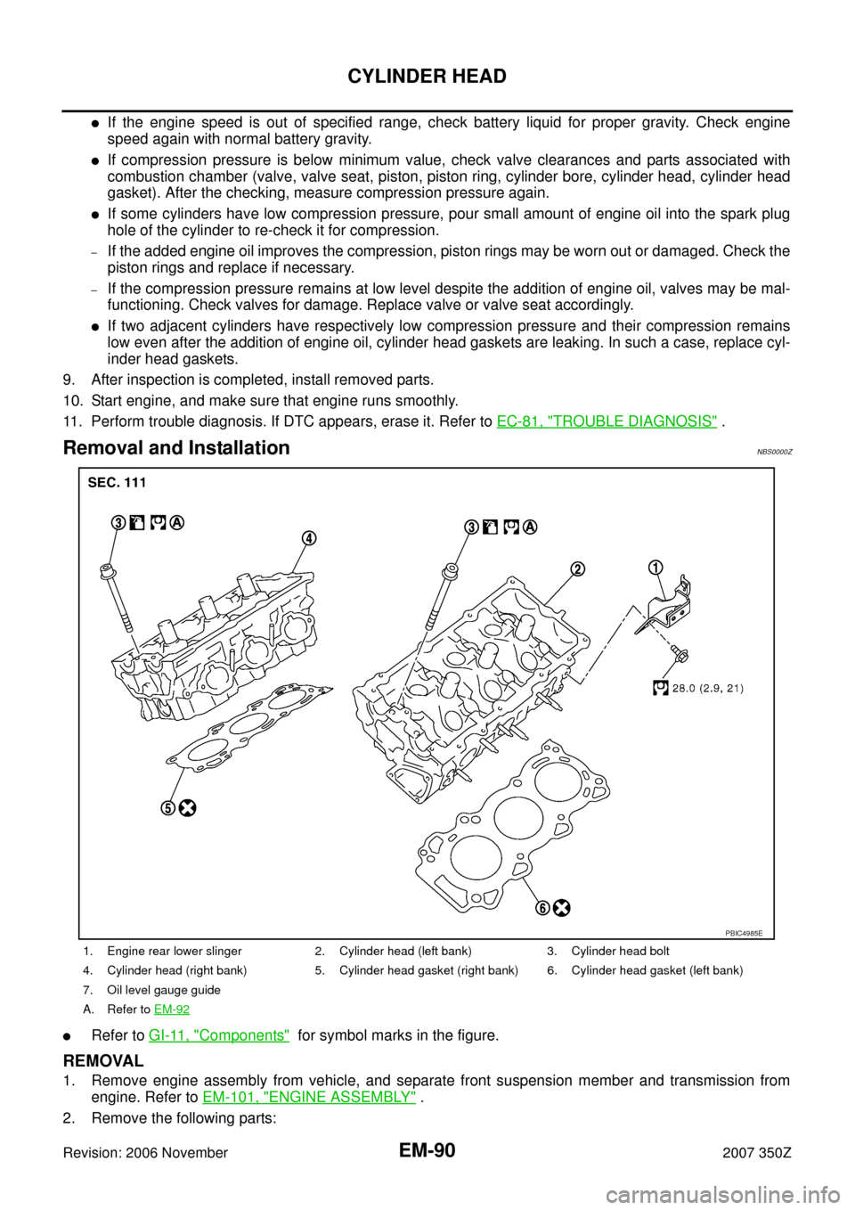
Removal and InstallationNBS0000Z
�Refer to GI-11, "Components" for symbol marks in the figure.
REMOVAL
1. Remove engine assembly from vehicle, and separate front suspension member and transmission from
engine. Refer to EM-101, "
ENGINE ASSEMBLY" .
2. Remove the following parts:
1. Engine rear lower slinger 2. Cylinder head (left bank) 3. Cylinder head bolt
4. Cylinder head (right bank) 5. Cylinder head gasket (right bank) 6. Cylinder head gasket (left bank)
7. Oil level gauge guide
A. Refer to EM-92
PBIC4985E
Page 93 of 148

CYLINDER HEAD
EM-93
C
D
E
F
G
H
I
J
K
L
MA
EM
Revision: 2006 November2007 350Z
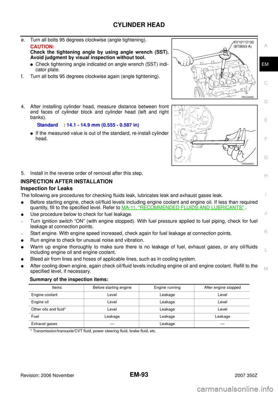
e. Turn all bolts 95 degrees clockwise (angle tightening).
CAUTION:
Check the tightening angle by using angle wrench (SST).
Avoid judgment by visual inspection without tool.
�Check tightening angle indicated on angle wrench (SST) indi-
cator plate.
f. Turn all bolts 95 degrees clockwise again (angle tightening).
4. After installing cylinder head, measure distance between front
end faces of cylinder block and cylinder head (left and right
banks).
�If the measured value is out of the standard, re-install cylinder
head.
5. Install in the reverse order of removal after this step.
INSPECTION AFTER INSTALLATION
Inspection for Leaks
The following are procedures for checking fluids leak, lubricates leak and exhaust gases leak.
�Before starting engine, check oil/fluid levels including engine coolant and engine oil. If less than required
quantity, fill to the specified level. Refer to MA-11, "
RECOMMENDED FLUIDS AND LUBRICANTS" .
�Use procedure below to check for fuel leakage.
–Turn ignition switch “ON” (with engine stopped). With fuel pressure applied to fuel piping, check for fuel
leakage at connection points.
–Start engine. With engine speed increased, check again for fuel leakage at connection points.
�Run engine to check for unusual noise and vibration.
�Warm up engine thoroughly to make sure there is no leakage of fuel, exhaust gases, or any oil/fluids
including engine oil and engine coolant.
�Bleed air from lines and hoses of applicable lines, such as in cooling system.
�After cooling down engine, again check oil/fluid levels including engine oil and engine coolant. Refill to the
specified level, if necessary.
Summary of the inspection items:
* Transmission/transaxle/CVT fluid, power steering fluid, brake fluid, etc.
PBIC0888E
Standard : 14.1 - 14.9 mm (0.555 - 0.587 in)
EMQ0662D
Items Before starting engine Engine running After engine stopped
Engine coolant Level Leakage Level
Engine oil Level Leakage Level
Other oils and fluid* Level Leakage Level
Fuel Leakage Leakage Leakage
Exhaust gases — Leakage —
Page 102 of 148

EM-102
ENGINE ASSEMBLY
Revision: 2006 November2007 350Z
REMOVAL
Outline
At first, remove engine and transmission assembly with front suspension member from vehicle downward.
Then separate engine from transmission.
Preparation
1. Release fuel pressure. Refer to EC-79, "FUEL PRESSURE RELEASE" .
2. Drain engine coolant from radiator. Refer to CO-10, "
Changing Engine Coolant" .
CAUTION:
�Perform this step when engine is cold.
�Do not spill engine coolant on drive belts.
3. Disconnect both battery cables. Refer to SC-4, "
BATTERY" .
4. Remove the following parts:
�Tower bar: Refer to FSU-20, "TOWER BAR" .
�Engine cover: Refer to EM-17, "INTAKE MANIFOLD COLLECTOR" .
�Cowl top cover (RH): Refer to EI-20, "COWL TOP" .
�Undercover
�Drive belts: Refer to EM-12, "DRIVE BELTS" .
�Front road wheels and tires
5. Remove air cleaner case and air duct. Refer to EM-15, "
AIR CLEANER AND AIR DUCT" .
6. Discharge refrigerant from A/C circuit. Refer to ATC-123, "
REFRIGERANT LINES" .
7. Remove radiator cooling fan assembly, reservoir tank and hoses. Refer to CO-21, "
COOLING FAN" and
CO-13, "
RADIATOR" .
Engine Room
1. Disconnect heater hose at engine-side, and fit a plug onto hose end to prevent engine coolant leak.
2. Disconnect ground cable (between vehicle to left cylinder head).
3. Disconnect battery positive cable harness at vehicle side and temporarily fasten it on engine.
4. Disconnect A/C piping from A/C compressor, and temporarily fasten it on vehicle with a rope.
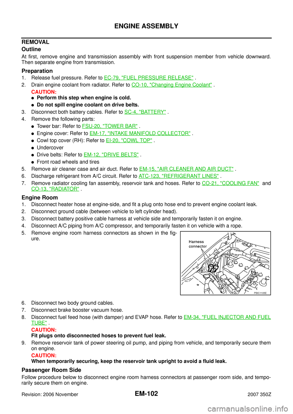
5. Remove engine room harness connectors as shown in the fig-
ure.
6. Disconnect two body ground cables.
7. Disconnect brake booster vacuum hose.
8. Disconnect fuel feed hose (with damper) and EVAP hose. Refer to EM-34, "
FUEL INJECTOR AND FUEL
TUBE" .
CAUTION:
Fit plugs onto disconnected hoses to prevent fuel leak.
9. Remove reservoir tank of power steering oil pump, and piping from vehicle, and temporarily secure them
on engine.
CAUTION:
When temporarily securing, keep the reservoir tank upright to avoid a fluid leak.
Passenger Room Side
Follow procedure below to disconnect engine room harness connectors at passenger room side, and tempo-
rarily secure them on engine.
PBIC1105E
Page 106 of 148

EM-106
ENGINE ASSEMBLY
Revision: 2006 November2007 350Z
INSPECTION AFTER INSTALLATION
Inspection for Leaks
The following are procedures for checking fluids leak, lubricates leak and exhaust gases leak.
�Before starting engine, check oil/fluid levels including engine coolant and engine oil. If less than required
quantity, fill to the specified level. Refer to MA-11, "
RECOMMENDED FLUIDS AND LUBRICANTS" .
�Use procedure below to check for fuel leakage.
–Turn ignition switch “ON” (with engine stopped). With fuel pressure applied to fuel piping, check for fuel
leakage at connection points.
–Start engine. With engine speed increased, check again for fuel leakage at connection points.
�Run engine to check for unusual noise and vibration.
�Warm up engine thoroughly to make sure there is no leakage of fuel, exhaust gases, or any oil/fluids
including engine oil and engine coolant.
�Bleed air from lines and hoses of applicable lines, such as in cooling system.
�After cooling down engine, again check oil/fluid levels including engine oil and engine coolant. Refill to the
specified level, if necessary.
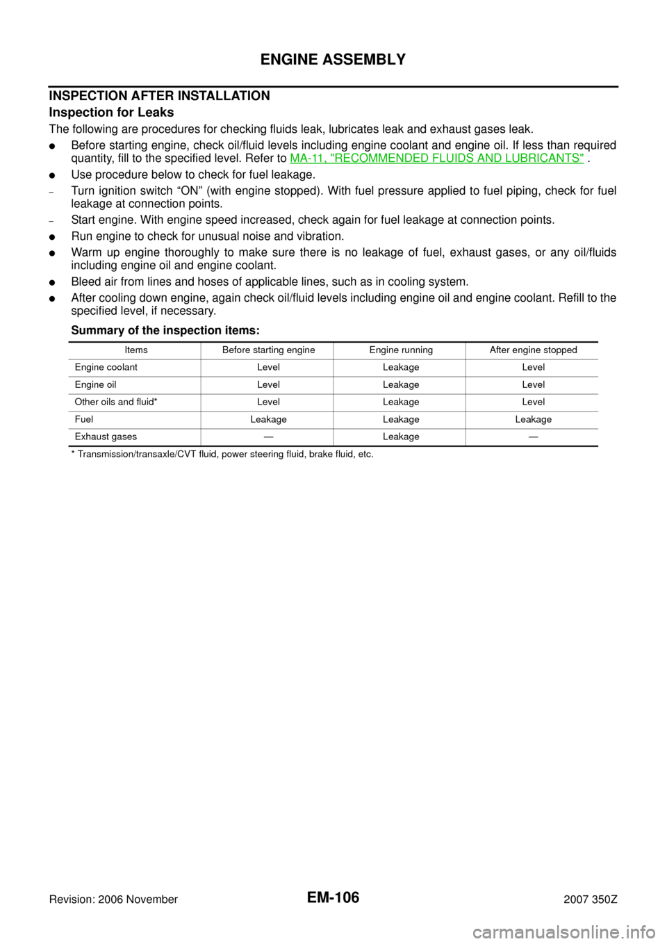
Summary of the inspection items:
* Transmission/transaxle/CVT fluid, power steering fluid, brake fluid, etc.Items Before starting engine Engine running After engine stopped
Engine coolant Level Leakage Level
Engine oil Level Leakage Level
Other oils and fluid* Level Leakage Level
Fuel Leakage Leakage Leakage
Exhaust gases — Leakage —