Page 93 of 148

CYLINDER HEAD
EM-93
C
D
E
F
G
H
I
J
K
L
MA
EM
Revision: 2006 November2007 350Z
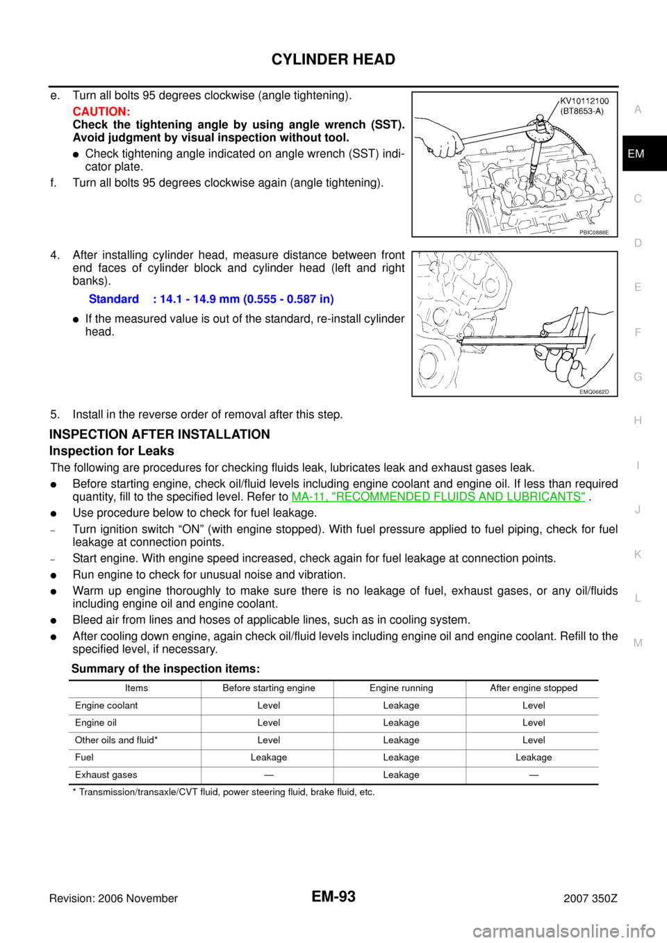
e. Turn all bolts 95 degrees clockwise (angle tightening).
CAUTION:
Check the tightening angle by using angle wrench (SST).
Avoid judgment by visual inspection without tool.
�Check tightening angle indicated on angle wrench (SST) indi-
cator plate.
f. Turn all bolts 95 degrees clockwise again (angle tightening).
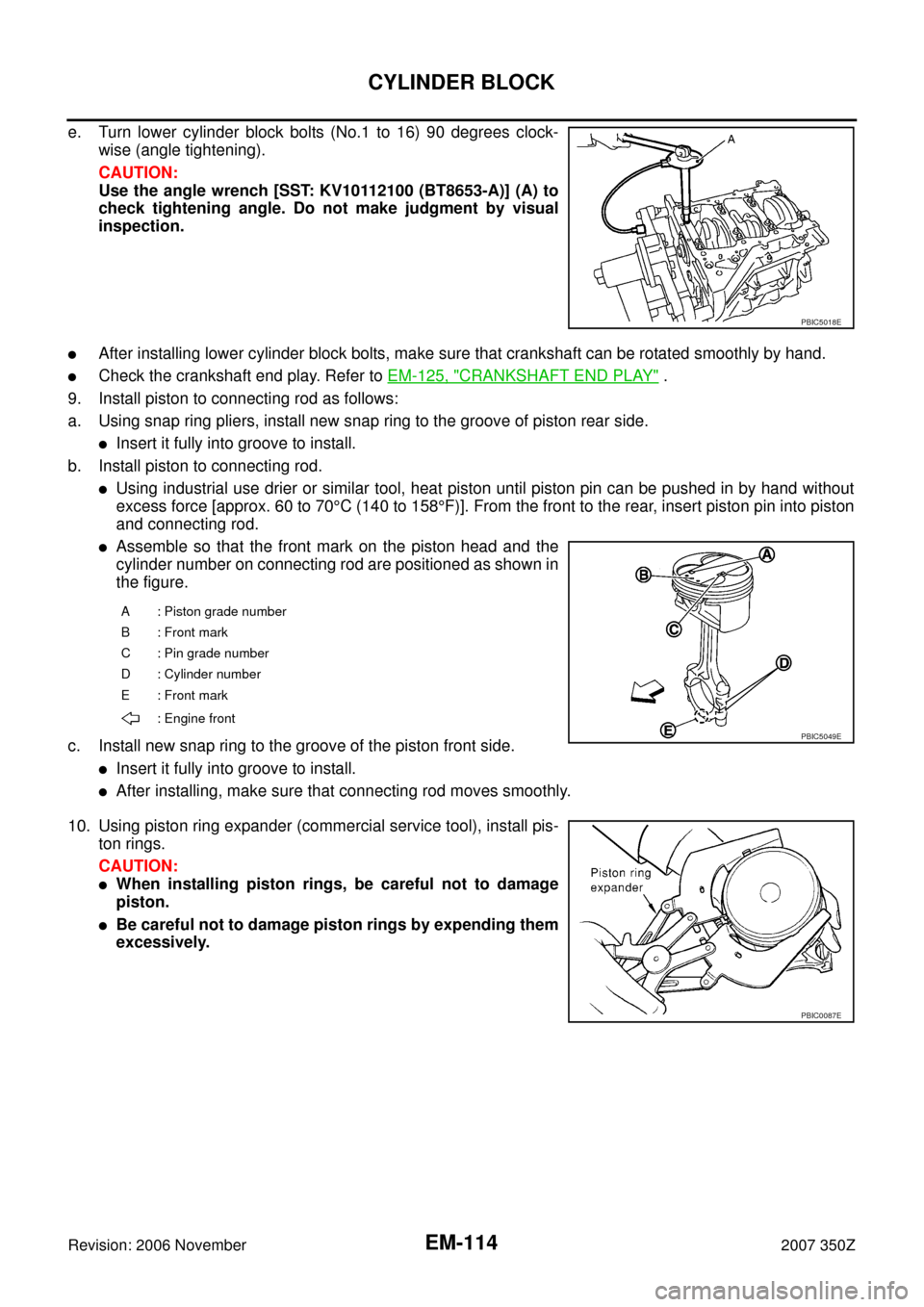
4. After installing cylinder head, measure distance between front
end faces of cylinder block and cylinder head (left and right
banks).
�If the measured value is out of the standard, re-install cylinder
head.
5. Install in the reverse order of removal after this step.
INSPECTION AFTER INSTALLATION
Inspection for Leaks
The following are procedures for checking fluids leak, lubricates leak and exhaust gases leak.
�Before starting engine, check oil/fluid levels including engine coolant and engine oil. If less than required
quantity, fill to the specified level. Refer to MA-11, "
RECOMMENDED FLUIDS AND LUBRICANTS" .
�Use procedure below to check for fuel leakage.
–Turn ignition switch “ON” (with engine stopped). With fuel pressure applied to fuel piping, check for fuel
leakage at connection points.
–Start engine. With engine speed increased, check again for fuel leakage at connection points.
�Run engine to check for unusual noise and vibration.
�Warm up engine thoroughly to make sure there is no leakage of fuel, exhaust gases, or any oil/fluids
including engine oil and engine coolant.
�Bleed air from lines and hoses of applicable lines, such as in cooling system.
�After cooling down engine, again check oil/fluid levels including engine oil and engine coolant. Refill to the
specified level, if necessary.
Summary of the inspection items:
* Transmission/transaxle/CVT fluid, power steering fluid, brake fluid, etc.
PBIC0888E
Standard : 14.1 - 14.9 mm (0.555 - 0.587 in)
EMQ0662D
Items Before starting engine Engine running After engine stopped
Engine coolant Level Leakage Level
Engine oil Level Leakage Level
Other oils and fluid* Level Leakage Level
Fuel Leakage Leakage Leakage
Exhaust gases — Leakage —
Page 114 of 148

EM-114
CYLINDER BLOCK
Revision: 2006 November2007 350Z
e. Turn lower cylinder block bolts (No.1 to 16) 90 degrees clock-
wise (angle tightening).
CAUTION:
Use the angle wrench [SST: KV10112100 (BT8653-A)] (A) to
check tightening angle. Do not make judgment by visual
inspection.
�After installing lower cylinder block bolts, make sure that crankshaft can be rotated smoothly by hand.
�Check the crankshaft end play. Refer to EM-125, "CRANKSHAFT END PLAY" .
9. Install piston to connecting rod as follows:
a. Using snap ring pliers, install new snap ring to the groove of piston rear side.
�Insert it fully into groove to install.
b. Install piston to connecting rod.
�Using industrial use drier or similar tool, heat piston until piston pin can be pushed in by hand without
excess force [approx. 60 to 70°C (140 to 158°F)]. From the front to the rear, insert piston pin into piston
and connecting rod.
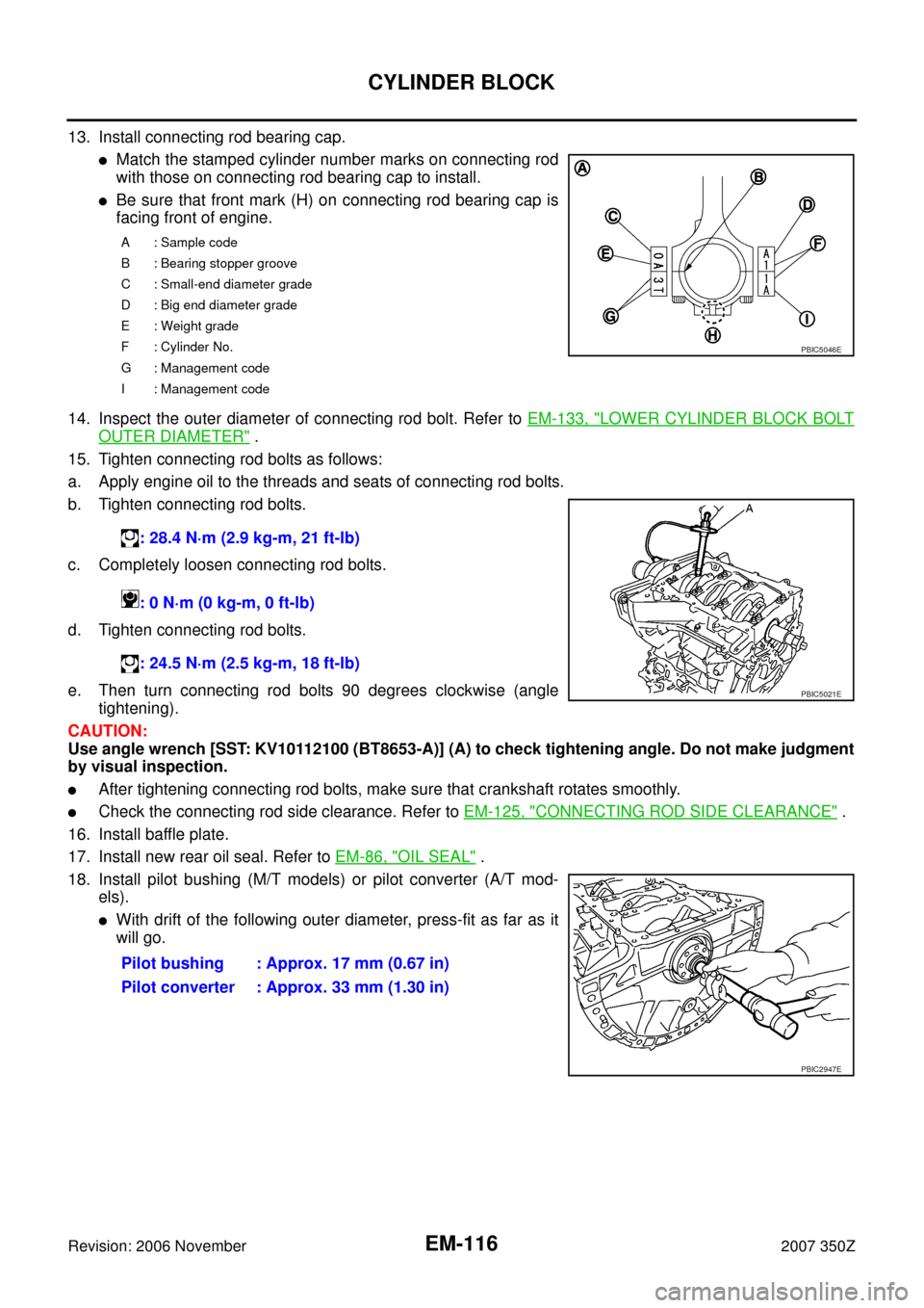
�Assemble so that the front mark on the piston head and the
cylinder number on connecting rod are positioned as shown in
the figure.
c. Install new snap ring to the groove of the piston front side.
�Insert it fully into groove to install.
�After installing, make sure that connecting rod moves smoothly.
10. Using piston ring expander (commercial service tool), install pis-
ton rings.
CAUTION:
�When installing piston rings, be careful not to damage
piston.
�Be careful not to damage piston rings by expending them
excessively.
PBIC5018E
A : Piston grade number
B : Front mark
C : Pin grade number
D : Cylinder number
E : Front mark
: Engine front
PBIC5049E
PBIC0087E
Page 116 of 148

EM-116
CYLINDER BLOCK
Revision: 2006 November2007 350Z
13. Install connecting rod bearing cap.
�Match the stamped cylinder number marks on connecting rod
with those on connecting rod bearing cap to install.
�Be sure that front mark (H) on connecting rod bearing cap is
facing front of engine.
14. Inspect the outer diameter of connecting rod bolt. Refer to EM-133, "
LOWER CYLINDER BLOCK BOLT
OUTER DIAMETER" .
15. Tighten connecting rod bolts as follows:
a. Apply engine oil to the threads and seats of connecting rod bolts.
b. Tighten connecting rod bolts.
c. Completely loosen connecting rod bolts.
d. Tighten connecting rod bolts.
e. Then turn connecting rod bolts 90 degrees clockwise (angle
tightening).
CAUTION:
Use angle wrench [SST: KV10112100 (BT8653-A)] (A) to check tightening angle. Do not make judgment
by visual inspection.
�After tightening connecting rod bolts, make sure that crankshaft rotates smoothly.
�Check the connecting rod side clearance. Refer to EM-125, "CONNECTING ROD SIDE CLEARANCE" .
16. Install baffle plate.
17. Install new rear oil seal. Refer to EM-86, "
OIL SEAL" .
18. Install pilot bushing (M/T models) or pilot converter (A/T mod-
els).
�With drift of the following outer diameter, press-fit as far as it
will go.
A: Sample code
B : Bearing stopper groove
C : Small-end diameter grade
D : Big end diameter grade
E : Weight grade
F : Cylinder No.
G : Management code
I : Management code
: 28.4 N·m (2.9 kg-m, 21 ft-lb)
: 0 N·m (0 kg-m, 0 ft-lb)
: 24.5 N·m (2.5 kg-m, 18 ft-lb)
Pilot bushing : Approx. 17 mm (0.67 in)
Pilot converter : Approx. 33 mm (1.30 in)
PBIC5046E
PBIC5021E
PBIC2947E