Page 357 of 720
DTC P0197, P0198 EOT SENSOR
EC-357
C
D
E
F
G
H
I
J
K
L
MA
EC
Revision: 2006 November2007 350Z
Wiring DiagramNBS006TT
TBWT1684E
Page 359 of 720

DTC P0197, P0198 EOT SENSOR
EC-359
C
D
E
F
G
H
I
J
K
L
MA
EC
Revision: 2006 November2007 350Z
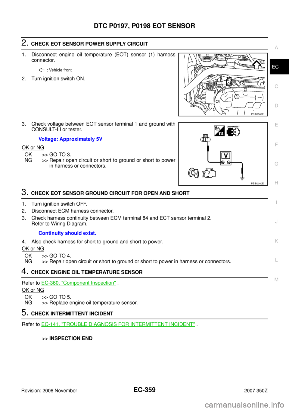
2. CHECK EOT SENSOR POWER SUPPLY CIRCUIT
1. Disconnect engine oil temperature (EOT) sensor (1) harness
connector.
2. Turn ignition switch ON.
3. Check voltage between EOT sensor terminal 1 and ground with
CONSULT-III or tester.
OK or NG
OK >> GO TO 3.
NG >> Repair open circuit or short to ground or short to power
in harness or connectors.
3. CHECK EOT SENSOR GROUND CIRCUIT FOR OPEN AND SHORT
1. Turn ignition switch OFF.
2. Disconnect ECM harness connector.
3. Check harness continuity between ECM terminal 84 and ECT sensor terminal 2.
Refer to Wiring Diagram.
4. Also check harness for short to ground and short to power.
OK or NG
OK >> GO TO 4.
NG >> Repair open circuit or short to ground or short to power in harness or connectors.
4. CHECK ENGINE OIL TEMPERATURE SENSOR
Refer to EC-360, "
Component Inspection" .
OK or NG
OK >> GO TO 5.
NG >> Replace engine oil temperature sensor.
5. CHECK INTERMITTENT INCIDENT
Refer to EC-141, "
TROUBLE DIAGNOSIS FOR INTERMITTENT INCIDENT" .
>>INSPECTION END
: Vehicle front
PBIB3562E
Voltage: Approximately 5V
PBIB0080E
Continuity should exist.
Page 363 of 720
DTC P0222, P0223, P2132, P2133 TP SENSOR
EC-363
C
D
E
F
G
H
I
J
K
L
MA
EC
Revision: 2006 November2007 350Z
Wiring DiagramNBS006V3
BANK 1
TBWT1641E
Page 368 of 720
EC-368
DTC P0222, P0223, P2132, P2133 TP SENSOR
Revision: 2006 November2007 350Z
2. CHECK THROTTLE POSITION SENSOR 1 POWER SUPPLY CIRCUIT-I
1. Disconnect electric throttle control actuator harness connector.
2. Turn ignition switch ON.
3. Check voltage between electric throttle control actuator terminal 6 and ground with CONSULT-III or tester.
OK or NG
OK >> GO TO 3.
NG >> Repair open circuit or short to ground or short to power in harness.
3. CHECK THROTTLE POSITION SENSOR 1 POWER SUPPLY CIRCUIT-II
1. Turn ignition switch OFF.
2. Disconnect ECM harness connector.
3. Check harness continuity between electric throttle control actuator terminal 6 and ECM terminal 44 (bank
1) or 43 (bank 2).
Refer to Wiring Diagram.
OK or NG
OK >> GO TO 4.
NG >> Repair open circuit.
1. Electric throttle control actuator
(bank 1)2. Electric throttle control actuator
(bank 2)
Voltage: Approximately 5V
PBIB3504E
PBIB3471E
Continuity should exist.
Page 369 of 720

DTC P0222, P0223, P2132, P2133 TP SENSOR
EC-369
C
D
E
F
G
H
I
J
K
L
MA
EC
Revision: 2006 November2007 350Z
4. CHECK THROTTLE POSITION SENSOR 1 GROUND CIRCUIT FOR OPEN AND SHORT
1. Turn ignition switch OFF.
2. Disconnect ECM harness connector.
3. Check harness continuity between electric throttle control actuator terminal 3 and ECM terminal 40 (bank
1) or 48 (bank 2). Refer to Wiring Diagram.
4. Also check harness for short to ground and short to power.
OK or NG
OK >> GO TO 5.
NG >> Repair open circuit or short to ground or short to power in harness or connectors.
5. CHECK THROTTLE POSITION SENSOR 1 INPUT SIGNAL CIRCUIT FOR OPEN AND SHORT
1. Check harness continuity between ECM terminal 30 (bank 1) or 31 (bank 2) and electric throttle control
actuator terminal 4. Refer to Wiring Diagram.
2. Also check harness for short to ground and short to power.
OK or NG
OK >> GO TO 6.
NG >> Repair open circuit or short to ground or short to power in harness or connectors.
6. CHECK THROTTLE POSITION SENSOR
Refer to EC-369, "
Component Inspection" .
OK or NG
OK >> GO TO 8.
NG >> GO TO 7.
7. REPLACE ELECTRIC THROTTLE CONTROL ACTUATOR
1. Replace the electric throttle control actuator.
2. Perform EC-77, "
Throttle Valve Closed Position Learning" .
3. Perform EC-77, "
Idle Air Volume Learning" .
>>INSPECTION END
8. CHECK INTERMITTENT INCIDENT
Refer to EC-141, "
TROUBLE DIAGNOSIS FOR INTERMITTENT INCIDENT" .
>>INSPECTION END
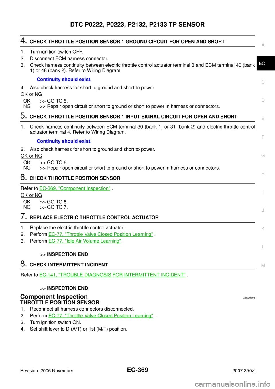
Component InspectionNBS006V4
THROTTLE POSITION SENSOR
1. Reconnect all harness connectors disconnected.
2. Perform EC-77, "
Throttle Valve Closed Position Learning" .
3. Turn ignition switch ON.
4. Set shift lever to D (A/T) or 1st (M/T) position. Continuity should exist.
Continuity should exist.
Page 377 of 720

DTC P0300 - P0306 MULTIPLE CYLINDER MISFIRE, NO. 1 - 6 CYLINDER MIS-
FIRE
EC-377
C
D
E
F
G
H
I
J
K
L
MA
EC
Revision: 2006 November2007 350Z
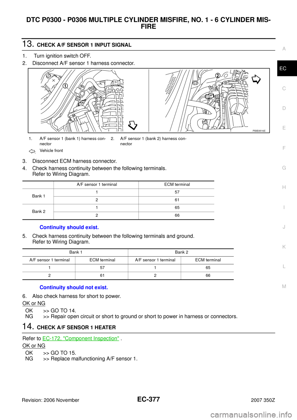
13. CHECK A/F SENSOR 1 INPUT SIGNAL
1. Turn ignition switch OFF.
2. Disconnect A/F sensor 1 harness connector.
3. Disconnect ECM harness connector.
4. Check harness continuity between the following terminals.
Refer to Wiring Diagram.
5. Check harness continuity between the following terminals and ground.
Refer to Wiring Diagram.
6. Also check harness for short to power.
OK or NG
OK >> GO TO 14.
NG >> Repair open circuit or short to ground or short to power in harness or connectors.
14. CHECK A/F SENSOR 1 HEATER
Refer to EC-172, "
Component Inspection" .
OK or NG
OK >> GO TO 15.
NG >> Replace malfunctioning A/F sensor 1.
1. A/F sensor 1 (bank 1) harness con-
nector2. A/F sensor 1 (bank 2) harness con-
nector
:Vehicle front
A/F sensor 1 terminal ECM terminal
Bank 1157
261
Bank 2165
266
Continuity should exist.
Bank 1 Bank 2
A/F sensor 1 terminal ECM terminal A/F sensor 1 terminal ECM terminal
157165
261266
Continuity should not exist.
PBIB3516E
Page 380 of 720
EC-380
DTC P0327, P0328, P0332, P0333 KS
Revision: 2006 November2007 350Z
Wiring DiagramNBS00080
BANK 1
TBWT1643E
Page 383 of 720

DTC P0327, P0328, P0332, P0333 KS
EC-383
C
D
E
F
G
H
I
J
K
L
MA
EC
Revision: 2006 November2007 350Z
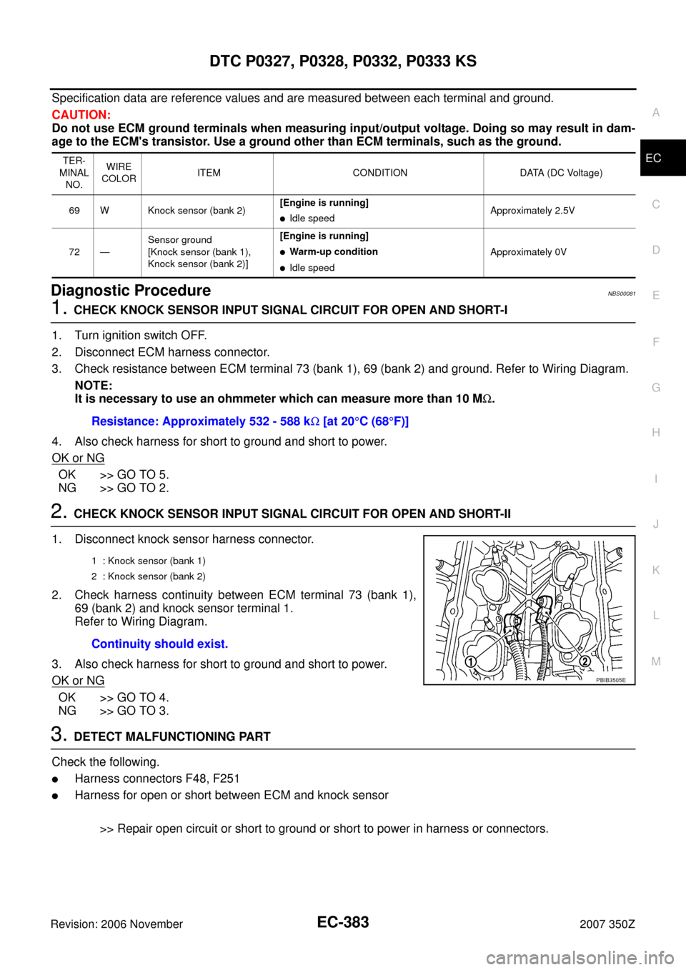
Specification data are reference values and are measured between each terminal and ground.
CAUTION:
Do not use ECM ground terminals when measuring input/output voltage. Doing so may result in dam-
age to the ECM's transistor. Use a ground other than ECM terminals, such as the ground.
Diagnostic ProcedureNBS00081
1. CHECK KNOCK SENSOR INPUT SIGNAL CIRCUIT FOR OPEN AND SHORT-I
1. Turn ignition switch OFF.
2. Disconnect ECM harness connector.
3. Check resistance between ECM terminal 73 (bank 1), 69 (bank 2) and ground. Refer to Wiring Diagram.
NOTE:
It is necessary to use an ohmmeter which can measure more than 10 MΩ.
4. Also check harness for short to ground and short to power.
OK or NG
OK >> GO TO 5.
NG >> GO TO 2.
2. CHECK KNOCK SENSOR INPUT SIGNAL CIRCUIT FOR OPEN AND SHORT-II
1. Disconnect knock sensor harness connector.
2. Check harness continuity between ECM terminal 73 (bank 1),
69 (bank 2) and knock sensor terminal 1.
Refer to Wiring Diagram.
3. Also check harness for short to ground and short to power.
OK or NG
OK >> GO TO 4.
NG >> GO TO 3.
3. DETECT MALFUNCTIONING PART
Check the following.
�Harness connectors F48, F251
�Harness for open or short between ECM and knock sensor
>> Repair open circuit or short to ground or short to power in harness or connectors.
TER-
MINAL
NO.WIRE
COLORITEM CONDITION DATA (DC Voltage)
69 W Knock sensor (bank 2)[Engine is running]
�Idle speedApproximately 2.5V
72 —Sensor ground
[Knock sensor (bank 1),
Knock sensor (bank 2)][Engine is running]
�Warm-up condition
�Idle speedApproximately 0V
Resistance: Approximately 532 - 588 kΩ [at 20°C (68°F)]
1 : Knock sensor (bank 1)
2 : Knock sensor (bank 2)
Continuity should exist.
PBIB3505E