Page 598 of 720
EC-598
DTC P1290, P2100, P2103 THROTTLE CONTROL MOTOR RELAY
Revision: 2006 November2007 350Z
2. CHECK THROTTLE CONTROL MOTOR RELAY POWER SUPPLY CIRCUIT-II
1. Disconnect ECM harness connector.
2. Disconnect IPDM E/R harness connector E9.
3. Check continuity between ECM terminal 25 and IPDM E/R terminal 47.
Refer to Wiring Diagram.
4. Also check harness for short to ground and short to power.
OK or NG
OK >> GO TO 4.
NG >> GO TO 3.
3. DETECT MALFUNCTIONING PART
Check the following.
�Harness connectors E10, F1
�Harness for open or short between ECM and IPDM E/R
>> Repair open circuit or short to ground or short to power in harness or connectors.
4. CHECK FUSE
1. Disconnect 15A fuse.
2. Check 15A fuse for blown.
OK or NG
OK >> GO TO 8.
NG >> Replace 15A fuse.
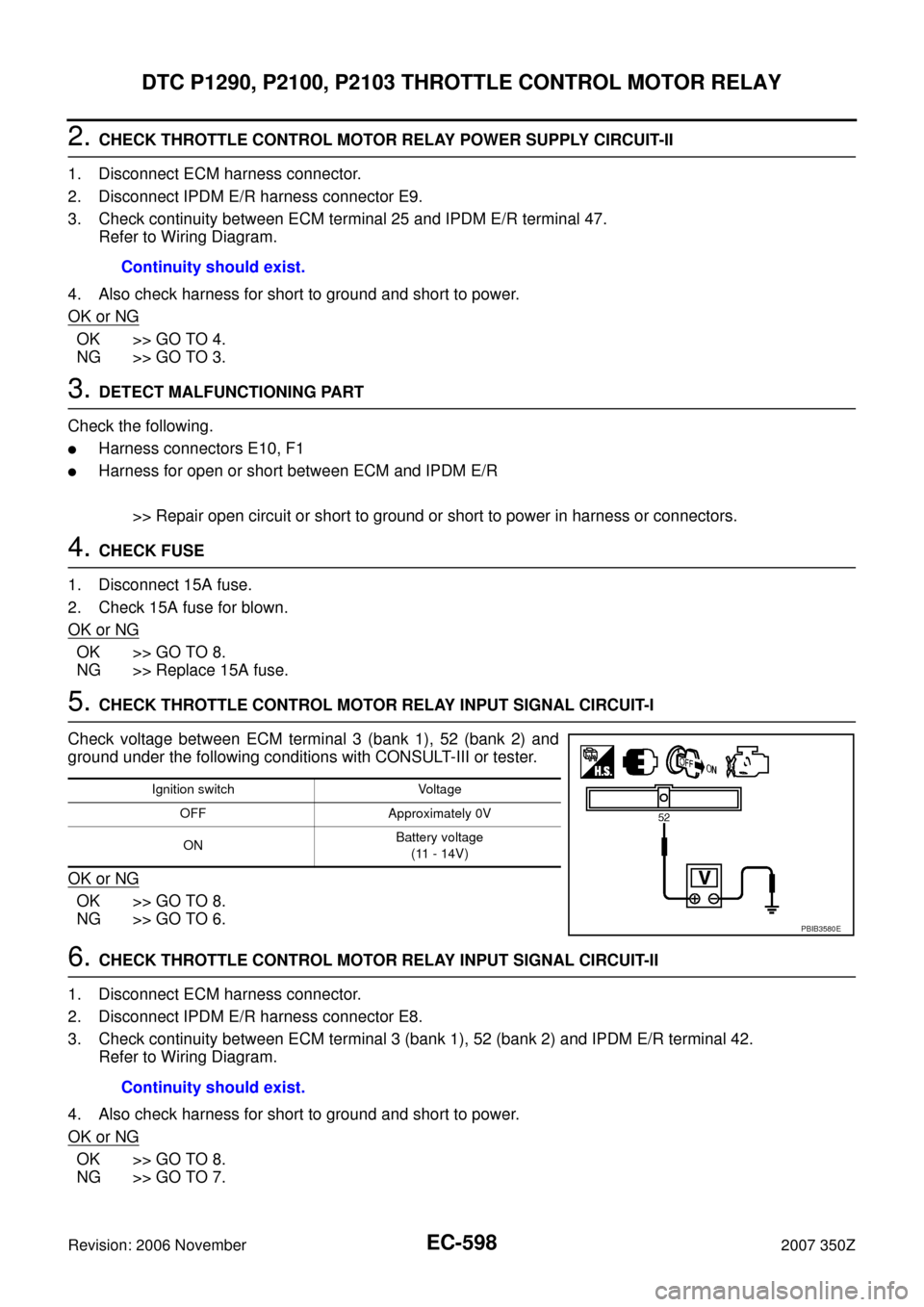
5. CHECK THROTTLE CONTROL MOTOR RELAY INPUT SIGNAL CIRCUIT-I
Check voltage between ECM terminal 3 (bank 1), 52 (bank 2) and
ground under the following conditions with CONSULT-III or tester.
OK or NG
OK >> GO TO 8.
NG >> GO TO 6.
6. CHECK THROTTLE CONTROL MOTOR RELAY INPUT SIGNAL CIRCUIT-II
1. Disconnect ECM harness connector.
2. Disconnect IPDM E/R harness connector E8.
3. Check continuity between ECM terminal 3 (bank 1), 52 (bank 2) and IPDM E/R terminal 42.
Refer to Wiring Diagram.
4. Also check harness for short to ground and short to power.
OK or NG
OK >> GO TO 8.
NG >> GO TO 7.Continuity should exist.
Ignition switch Voltage
OFF Approximately 0V
ONBattery voltage
(11 - 14V)
PBIB3580E
Continuity should exist.
Page 607 of 720
DTC P1564 ASCD STEERING SWITCH
EC-607
C
D
E
F
G
H
I
J
K
L
MA
EC
Revision: 2006 November2007 350Z
2. CHECK ASCD STEERING SWITCH CIRCUIT
With CONSULT-III
1. Turn ignition switch ON.
2. Select “MAIN SW”, “RESUME/ACC SW”, “SET SW” and “CANCEL SW” in “DATA MONITOR” mode with
CONSULT-III.
3. Check each item indication under the following conditions.
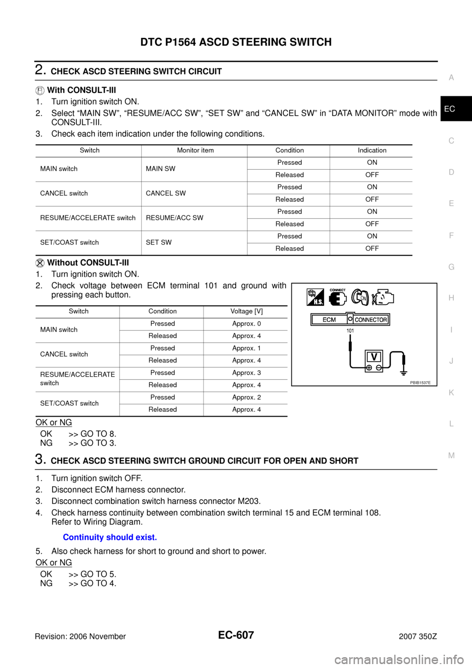
Without CONSULT-III
1. Turn ignition switch ON.
2. Check voltage between ECM terminal 101 and ground with
pressing each button.
OK or NG
OK >> GO TO 8.
NG >> GO TO 3.
3. CHECK ASCD STEERING SWITCH GROUND CIRCUIT FOR OPEN AND SHORT
1. Turn ignition switch OFF.
2. Disconnect ECM harness connector.
3. Disconnect combination switch harness connector M203.
4. Check harness continuity between combination switch terminal 15 and ECM terminal 108.
Refer to Wiring Diagram.
5. Also check harness for short to ground and short to power.
OK or NG
OK >> GO TO 5.
NG >> GO TO 4.
Switch Monitor item Condition Indication
MAIN switch MAIN SWPressed ON
Released OFF
CANCEL switch CANCEL SWPressed ON
Released OFF
RESUME/ACCELERATE switch RESUME/ACC SWPressed ON
Released OFF
SET/COAST switch SET SWPressed ON
Released OFF
Switch Condition Voltage [V]
MAIN switchPressed Approx. 0
Released Approx. 4
CANCEL switchPressed Approx. 1
Released Approx. 4
RESUME/ACCELERATE
switchPressed Approx. 3
Released Approx. 4
SET/COAST switchPressed Approx. 2
Released Approx. 4
PBIB1537E
Continuity should exist.
Page 608 of 720
EC-608
DTC P1564 ASCD STEERING SWITCH
Revision: 2006 November2007 350Z
4. DETECT MALFUNCTIONING PART
Check the following.
�Combination switch (spiral cable)
�Harness for open and short between ECM and combination switch
>> Repair open circuit or short to ground or short to power in harness or connectors.
5. CHECK ASCD STEERING SWITCH INPUT SIGNAL CIRCUIT FOR OPEN AND SHORT
1. Check harness continuity between ECM terminal 101 and combination switch terminal 14.
Refer to Wiring Diagram.
2. Also check harness for short to ground and short to power.
OK or NG
OK >> GO TO 7.
NG >> GO TO 6.
6. DETECT MALFUNCTIONING PART
Check the following.
�Combination switch (spiral cable)
�Harness for open and short between ECM and combination switch
>> Repair open circuit or short to ground or short to power in harness or connectors.
7. CHECK ASCD STEERING SWITCH
Refer to EC-609, "
Component Inspection" .
OK or NG
OK >> GO TO 8.
NG >> Replace steering wheel.
8. CHECK INTERMITTENT INCIDENT
Refer to EC-141, "
TROUBLE DIAGNOSIS FOR INTERMITTENT INCIDENT" .
>>INSPECTION END Continuity should exist.
Page 617 of 720
DTC P1572 ASCD BRAKE SWITCH
EC-617
C
D
E
F
G
H
I
J
K
L
MA
EC
Revision: 2006 November2007 350Z
4. DETECT MALFUNCTIONING PART
Check the following.
�Fuse block (J/B) connector E101
�10A fuse
�Harness for open or short between ASCD brake switch and fuse
>> Repair open circuit or short to ground or short to power in harness or connectors.
5. CHECK ASCD BRAKE SWITCH INPUT SIGNAL CIRCUIT FOR OPEN AND SHORT
1. Turn ignition switch OFF.
2. Disconnect ECM harness connector.
3. Check harness continuity between ECM terminal 126 and ASCD brake switch terminal 2.
Refer to Wiring Diagram.
4. Also check harness for short to ground and short to power.
OK or NG
OK >> GO TO 7.
NG >> GO TO 6.
6. DETECT MALFUNCTIONING PART
Check the following.
�Harness connectors E108, M15
�Harness for open or short between ECM and ASCD brake switch
>> Repair open circuit or short to ground or short to power in harness or connectors.
7. CHECK ASCD BRAKE SWITCH
Refer to EC-624, "
Component Inspection"
OK or NG
OK >> GO TO 13.
NG >> Replace ASCD brake switch.Continuity should exist.
Page 618 of 720
EC-618
DTC P1572 ASCD BRAKE SWITCH
Revision: 2006 November2007 350Z
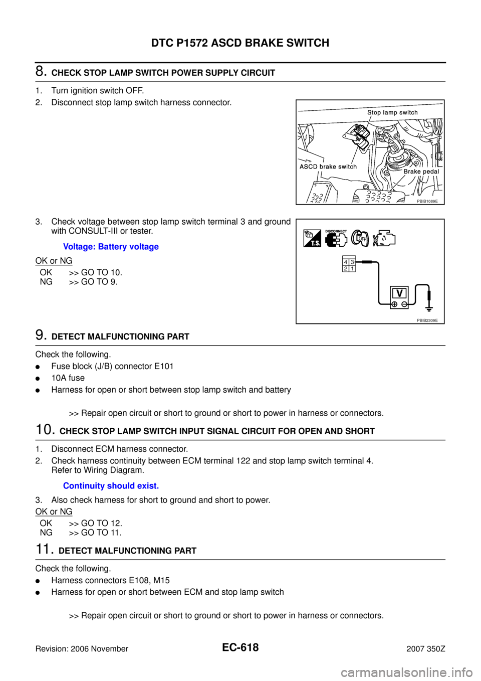
8. CHECK STOP LAMP SWITCH POWER SUPPLY CIRCUIT
1. Turn ignition switch OFF.
2. Disconnect stop lamp switch harness connector.
3. Check voltage between stop lamp switch terminal 3 and ground
with CONSULT-III or tester.
OK or NG
OK >> GO TO 10.
NG >> GO TO 9.
9. DETECT MALFUNCTIONING PART
Check the following.
�Fuse block (J/B) connector E101
�10A fuse
�Harness for open or short between stop lamp switch and battery
>> Repair open circuit or short to ground or short to power in harness or connectors.
10. CHECK STOP LAMP SWITCH INPUT SIGNAL CIRCUIT FOR OPEN AND SHORT
1. Disconnect ECM harness connector.
2. Check harness continuity between ECM terminal 122 and stop lamp switch terminal 4.
Refer to Wiring Diagram.
3. Also check harness for short to ground and short to power.
OK or NG
OK >> GO TO 12.
NG >> GO TO 11.
11 . DETECT MALFUNCTIONING PART
Check the following.
�Harness connectors E108, M15
�Harness for open or short between ECM and stop lamp switch
>> Repair open circuit or short to ground or short to power in harness or connectors.
PBIB1089E
Voltage: Battery voltage
PBIB2309E
Continuity should exist.
Page 622 of 720
EC-622
DTC P1572 ASCD BRAKE SWITCH
Revision: 2006 November2007 350Z
8. CHECK ASCD CLUTCH SWITCH INPUT SIGNAL CIRCUIT FOR OPEN AND SHORT
1. Turn ignition switch OFF.
2. Disconnect ECM harness connector.
3. Check harness continuity between ASCD clutch switch terminal 2 and ECM terminal 126.
Refer to Wiring Diagram.
4. Also check harness for short to ground and short to power.
OK or NG
OK >> GO TO 10.
NG >> GO TO 9.
9. DETECT MALFUNCTIONING PART
Check the following.
�Harness connectors E108, M15
�Harness for open or short between ECM and ASCD clutch switch
>> Repair open circuit or short to ground or short to power in harness or connectors.
10. CHECK ASCD CLUTCH SWITCH
Refer to EC-624, "
Component Inspection" .
OK or NG
OK >> GO TO 16.
NG >> Replace ASCD clutch switch.
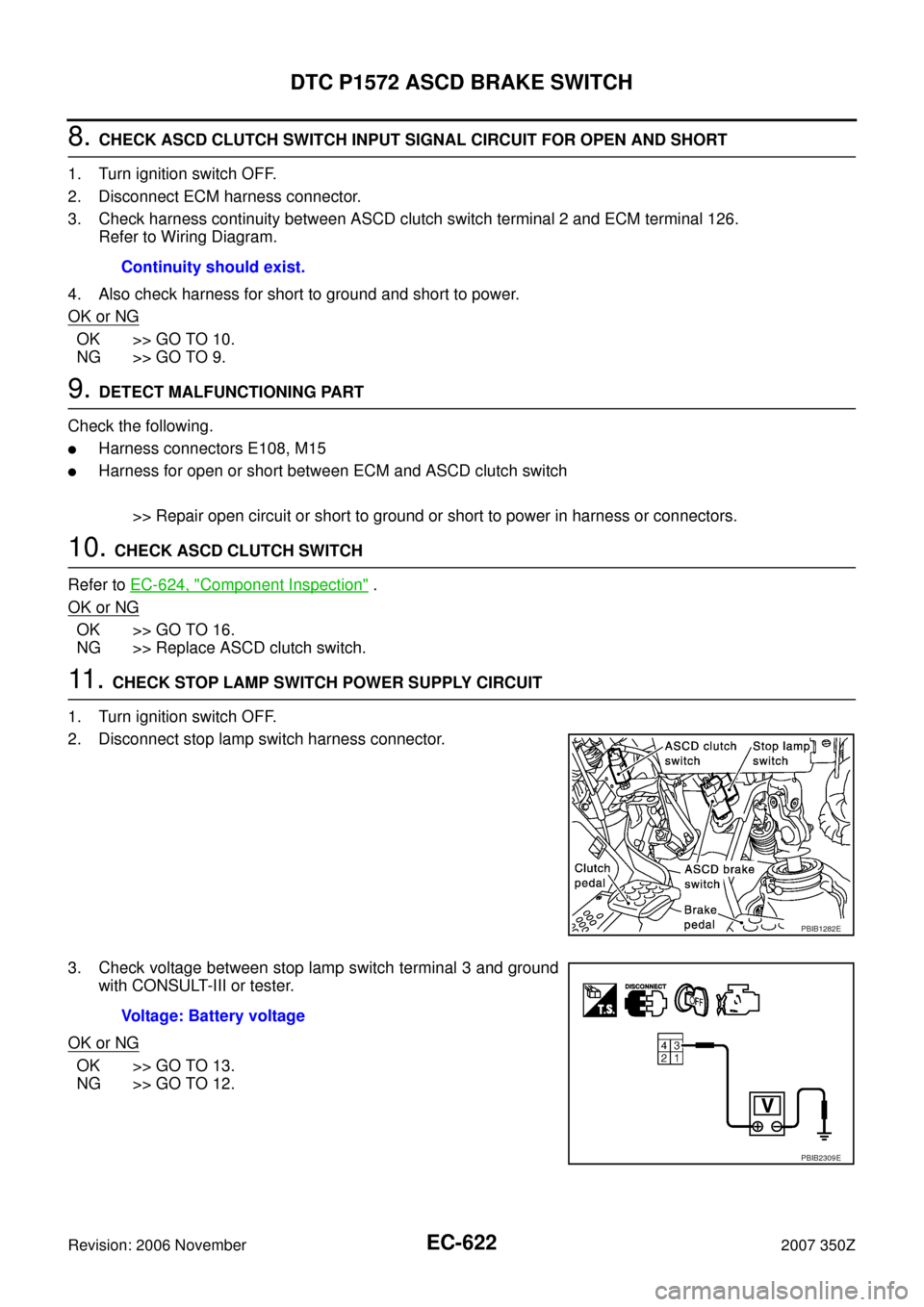
11 . CHECK STOP LAMP SWITCH POWER SUPPLY CIRCUIT
1. Turn ignition switch OFF.
2. Disconnect stop lamp switch harness connector.
3. Check voltage between stop lamp switch terminal 3 and ground
with CONSULT-III or tester.
OK or NG
OK >> GO TO 13.
NG >> GO TO 12.Continuity should exist.
PBIB1282E
Voltage: Battery voltage
PBIB2309E
Page 623 of 720
DTC P1572 ASCD BRAKE SWITCH
EC-623
C
D
E
F
G
H
I
J
K
L
MA
EC
Revision: 2006 November2007 350Z
12. DETECT MALFUNCTIONING PART
Check the following.
�Fuse block (J/B) connector E101
�10A fuse
�Harness for open or short between stop lamp switch and battery
>> Repair open circuit or short to ground or short to power in harness or connectors.
13. CHECK STOP LAMP SWITCH INPUT SIGNAL CIRCUIT FOR OPEN AND SHORT
1. Disconnect ECM harness connector.
2. Check harness continuity between ECM terminal 122 and stop lamp switch terminal 4.
Refer to Wiring Diagram.
3. Also check harness for short to ground and short to power.
OK or NG
OK >> GO TO 15.
NG >> GO TO 14.
14. DETECT MALFUNCTIONING PART
Check the following.
�Harness connectors E108, M15
�Harness for open or short between ECM and stop lamp switch
>> Repair open circuit or short to ground or short to power in harness or connectors.
15. CHECK STOP LAMP SWITCH
Refer to EC-624, "
Component Inspection"
OK or NG
OK >> GO TO 16.
NG >> Replace stop lamp switch.
16. CHECK INTERMITTENT INCIDENT
Refer to EC-141, "
TROUBLE DIAGNOSIS FOR INTERMITTENT INCIDENT" .
>>INSPECTION END Continuity should exist.
Page 631 of 720
DTC P1805 BRAKE SWITCH
EC-631
C
D
E
F
G
H
I
J
K
L
MA
EC
Revision: 2006 November2007 350Z
3. DETECT MALFUNCTIONING PART
Check the following.
�10A fuse
�Fuse block (J/B) connector E101
�Harness for open and short between stop lamp switch and fuse
>> Repair open circuit or short to ground or short to power in harness or connectors.
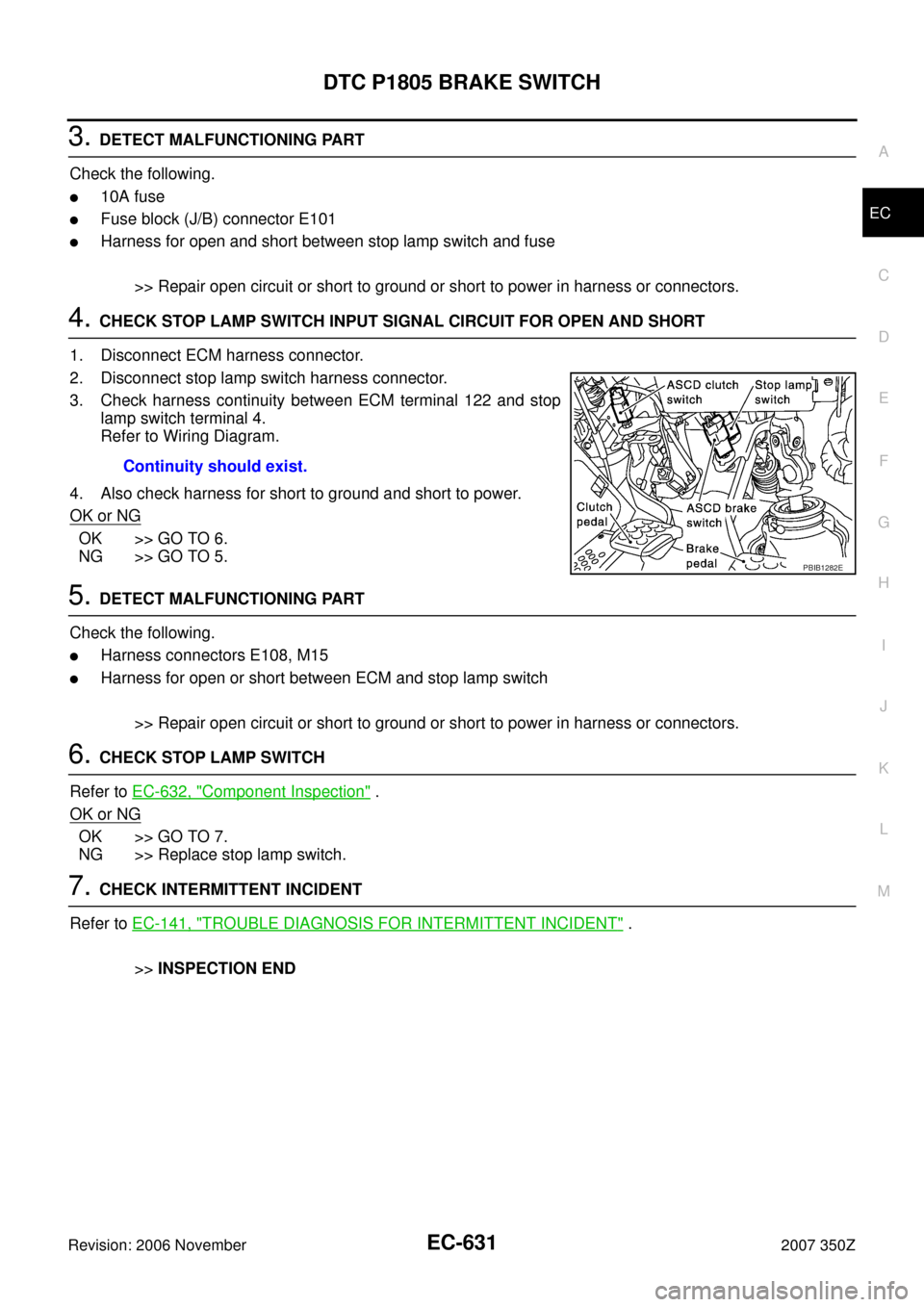
4. CHECK STOP LAMP SWITCH INPUT SIGNAL CIRCUIT FOR OPEN AND SHORT
1. Disconnect ECM harness connector.
2. Disconnect stop lamp switch harness connector.
3. Check harness continuity between ECM terminal 122 and stop
lamp switch terminal 4.
Refer to Wiring Diagram.
4. Also check harness for short to ground and short to power.
OK or NG
OK >> GO TO 6.
NG >> GO TO 5.
5. DETECT MALFUNCTIONING PART
Check the following.
�Harness connectors E108, M15
�Harness for open or short between ECM and stop lamp switch
>> Repair open circuit or short to ground or short to power in harness or connectors.
6. CHECK STOP LAMP SWITCH
Refer to EC-632, "
Component Inspection" .
OK or NG
OK >> GO TO 7.
NG >> Replace stop lamp switch.
7. CHECK INTERMITTENT INCIDENT
Refer to EC-141, "
TROUBLE DIAGNOSIS FOR INTERMITTENT INCIDENT" .
>>INSPECTION END Continuity should exist.
PBIB1282E