Page 536 of 720

EC-536
DTC P1078 P1084 EVT CONTROL POSITION SENSOR
Revision: 2006 November2007 350Z
4. CHECK EXHAUST VALVE TIMING CONTROL POSITION SENSOR POWER SUPPLY CIRCUIT-III
Check harness for short to power and short to ground, between the following terminals.
OK or NG
OK >> GO TO 5.
NG >> Repair short to ground or short to power in harness or connectors.
5. CHECK COMPONENTS
Check the following.
�Crankshaft position sensor (POS) (Refer to EC-393, "Component Inspection" .)
�Camshaft position sensor (PHASE) (bank 2) (Refer to EC-405, "Component Inspection" .)
�EVAP control system pressure sensor (Refer to EC-464, "Component Inspection" .)
�Refrigerant pressure sensor (Refer to AT C - 8 0 , "COMPONENT INSPECTION" .)
OK or NG
OK >> GO TO 6.
NG >> Replace malfunctioning component.
6. CHECK APP SENSOR
Refer to EC-648, "
Component Inspection" .
OK or NG
OK >> GO TO 14.
NG >> GO TO 7.
7. REPLACE ACCELERATOR PEDAL ASSEMBLY
1. Replace accelerator pedal assembly.
2. Perform EC-77, "
Accelerator Pedal Released Position Learning" .
3. Perform EC-77, "
Throttle Valve Closed Position Learning" .
4. Perform EC-77, "
Idle Air Volume Learning" .
>>INSPECTION END
ECM terminal Sensor terminal Reference Wiring Diagram
46 CKP sensor (POS) terminal 1EC-388
64CMP sensor (PHASE) (bank 2) terminal 1EC-399EVT control position sensor (bank 2) terminal 1EC-532
103 APP sensor terminal 4EC-643
107 EVAP control system pressure sensor terminal 3EC-458
111 Refrigerant pressure sensor terminal 1EC-711
Page 537 of 720

DTC P1078 P1084 EVT CONTROL POSITION SENSOR
EC-537
C
D
E
F
G
H
I
J
K
L
MA
EC
Revision: 2006 November2007 350Z
8. CHECK EXHAUST VALVE TIMING CONTROL POSITION SENSOR GROUND CIRCUIT FOR OPEN
AND SHORT
1. Turn ignition switch OFF.
2. Disconnect ECM harness connector.
3. Check harness continuity between exhaust valve timing control position sensor terminal 2 and ECM termi-
nal 88. Refer to Wiring Diagram.
4. Also check harness for short to ground and short to power.
OK or NG
OK >> GO TO 9.
NG >> Repair open circuit or short to ground or short to power in harness or connectors..
9. CHECK EXHAUST VALVE TIMING CONTROL POSITION SENSOR INPUT SIGNAL CIRCUIT FOR
OPEN AND SHORT
1. Check harness continuity between ECM terminal 58 (bank 1) or 62 (bank 2) and exhaust valve timing con-
trol position sensor terminal 3.
Refer to Wiring Diagram.
2. Also check harness for short to ground and short to power.
OK or NG
OK >> GO TO 10.
NG >> Repair open circuit or short to ground or short to power in harness or connectors.
10. CHECK EXHAUST VALVE TIMING CONTROL POSITION SENSOR
Refer to EC-539, "
Component Inspection" .
OK or NG
OK >> GO TO 11.
NG >> Replace exhaust valve timing control position sensor.
11 . CHECK CRANKSHAFT POSITION SENSOR (POS)
Refer to EC-393, "
Component Inspection" .
OK or NG
OK >> GO TO 12.
NG >> Replace crankshaft position sensor (POS).
12. CHECK CAMSHAFT POSITION SENSOR (PHASE)
Refer to EC-405, "
Component Inspection" .
OK or NG
OK >> GO TO 13.
NG >> Replace malfunctioning camshaft position sensor (PHASE).Continuity should exist.
Continuity should exist.
Page 538 of 720
EC-538
DTC P1078 P1084 EVT CONTROL POSITION SENSOR
Revision: 2006 November2007 350Z
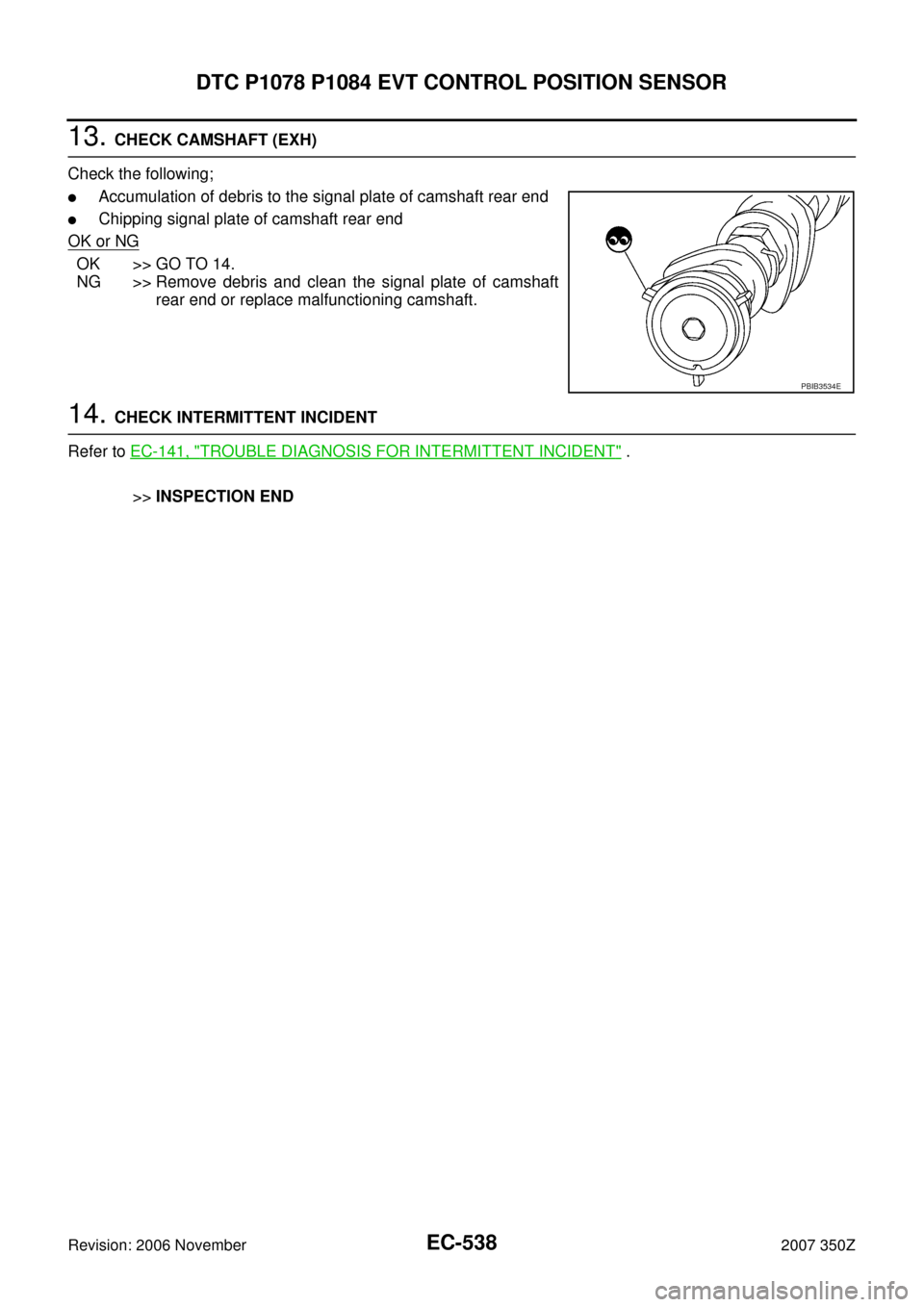
13. CHECK CAMSHAFT (EXH)
Check the following;
�Accumulation of debris to the signal plate of camshaft rear end
�Chipping signal plate of camshaft rear end
OK or NG
OK >> GO TO 14.
NG >> Remove debris and clean the signal plate of camshaft
rear end or replace malfunctioning camshaft.
14. CHECK INTERMITTENT INCIDENT
Refer to EC-141, "
TROUBLE DIAGNOSIS FOR INTERMITTENT INCIDENT" .
>>INSPECTION END
PBIB3534E
Page 539 of 720
DTC P1078 P1084 EVT CONTROL POSITION SENSOR
EC-539
C
D
E
F
G
H
I
J
K
L
MA
EC
Revision: 2006 November2007 350Z
Component InspectionNBS000BP
EXHAUST VALVE TIMING CONTROL POSITION SENSOR
1. Disconnect exhaust valve timing control position sensor harness connector.
2. Loosen the fixing bolt of the sensor.
3. Remove the sensor.
4. Visually check the sensor for chipping.
5. Check resistance as shown below.
6. If NG, replace exhaust valve timing control position sensor.
Removal and InstallationNBS000BQ
EXHAUST VALVE TIMING CONTROL POSITION SENSOR
Refer to EM-72, "CAMSHAFT" .
PBIB3566E
Terminal No. (Polarity) Resistance Ω [at 25°C (77°F)]
1 (+) - 2 (-)
Except 0 or ∞ 1 (+) - 3 (-)
2 (+) - 3 (-)
PBIA9584J
Page 540 of 720
EC-540
DTC P1148, P1168 CLOSED LOOP CONTROL
Revision: 2006 November2007 350Z
DTC P1148, P1168 CLOSED LOOP CONTROLPFP:22690
On Board Diagnosis LogicNBS000D5
These self-diagnoses have the one trip detection logic.
NOTE:
DTC P1148 or P1168 is displayed with another DTC for air fuel ratio (A/F) sensor 1.
Perform the trouble diagnosis for the corresponding DTC.
DTC No. Trouble diagnosis name DTC detecting condition Possible cause
P1148
1148
(Bank 1)
Closed loop control
functionThe closed loop control function for bank 1
does not operate even when vehicle is driving
in the specified condition.
�Harness or connectors
[The air fuel ratio (A/F) sensor 1 circuit is
open or shorted.]
�Air fuel ratio (A/F) sensor 1
�Air fuel ratio (A/F) sensor 1 heater P1168
1168
(Bank 2)The closed loop control function for bank 2
does not operate even when vehicle is driving
in the specified condition.
Page 543 of 720

DTC P1217 ENGINE OVER TEMPERATURE
EC-543
C
D
E
F
G
H
I
J
K
L
MA
EC
Revision: 2006 November2007 350Z
DTC P1217 ENGINE OVER TEMPERATUREPFP:00000
DescriptionNBS000DE
SYSTEM DESCRIPTION
NOTE:
�If DTC P1217 is displayed with DTC U1000 or U1001, first perform the trouble diagnosis for DTC
U1000, U1001. Refer to EC-151, "
DTC U1000, U1001 CAN COMMUNICATION LINE" .
�If DTC P1217 is displayed with DTC U1010, first perform the trouble diagnosis for DTC U1010.
Refer to EC-154, "
DTC U1010 CAN COMMUNICATION" .
Cooling Fan Control
*1: The ECM determines the start signal status by the signals of engine speed and battery voltage.
*2: This signal is sent to ECM through CAN communication line.
The ECM controls the cooling fan corresponding to the vehicle speed, engine coolant temperature, refrigerant
pressure, and air conditioner ON signal. The control system has 3-step control [HIGH/LOW/OFF].
Cooling Fan Operation
Sensor Input Signal to ECM ECM function Actuator
Crankshaft position sensor (POS)
Camshaft position sensor (PHASE)Engine speed*
1
Cooling fan
controlIPDM E/R
(Cooling fan relays) Battery
Battery voltage*
1
Wheel sensor
Vehicle speed*2
Engine coolant temperature sensor Engine coolant temperature
Air conditioner switch
Air conditioner ON signal*
2
Refrigerant pressure sensor Refrigerant pressure
PBIB2483E
Page 546 of 720
EC-546
DTC P1217 ENGINE OVER TEMPERATURE
Revision: 2006 November2007 350Z
6. Make sure that cooling fans operates at low speed.
If NG, go to EC-549, "
Diagnostic Procedure" .
If OK, go to the following steps.
7. Turn ignition switch OFF.
8. Turn air conditioner switch and blower fan switch OFF.
9. Disconnect engine coolant temperature sensor harness connec-
tor.
10. Connect 150Ω resistor to engine coolant temperature sensor
harness connector.
11. Restart engine and make sure that cooling fans operates at
higher speed than low speed.
CAUTION:
Be careful not to overheat engine.
12. If NG, go to EC-549, "
Diagnostic Procedure" .
SEC163BA
MEC475B
Page 550 of 720

EC-550
DTC P1217 ENGINE OVER TEMPERATURE
Revision: 2006 November2007 350Z
5. CHECK COOLING FAN HIGH SPEED OPERATION
Without CONSULT-III
1. Turn ignition switch OFF.
2. Turn air conditioner switch and blower fan switch OFF.
3. Disconnect engine coolant temperature sensor harness connector.
4. Connect 150Ω resistor to engine coolant temperature sensor harness connector.
5. Restart engine and make sure that cooling fans-1 and -2 oper-
ate at higher speed than low speed.
OK or NG
OK >> GO TO 6.
NG >> Check cooling fan high speed control circuit. (Go to EC-
554, "PROCEDURE B" .)
6. CHECK COOLING SYSTEM FOR LEAK
Refer to CO-10, "
LEAK CHECK" .
OK or NG
OK >> GO TO 7.
NG >> Check the following for leak.
�Hose
�Radiator
�Water pump
7. CHECK RADIATOR CAP
Refer to CO-15, "
Checking Radiator Cap" .
OK or NG
OK >> GO TO 8.
NG >> Replace radiator cap.
8. CHECK THERMOSTAT
Refer to CO-26, "
WATER INLET AND THERMOSTAT ASSEMBLY" .
OK or NG
OK >> GO TO 9.
NG >> Replace thermostat
9. CHECK ENGINE COOLANT TEMPERATURE SENSOR
Refer to EC-228, "
Component Inspection" .
OK or NG
OK >> GO TO 10.
NG >> Replace engine coolant temperature sensor.
10. CHECK MAIN 12 CAUSES
If the cause cannot be isolated, go to EC-555, "
Main 12 Causes of Overheating" .
>>INSPECTION END
MEC475B