Page 388 of 720
EC-388
DTC P0335 CKP SENSOR (POS)
Revision: 2006 November2007 350Z
Wiring DiagramNBS00088
TBWT1645E
Page 389 of 720
DTC P0335 CKP SENSOR (POS)
EC-389
C
D
E
F
G
H
I
J
K
L
MA
EC
Revision: 2006 November2007 350Z
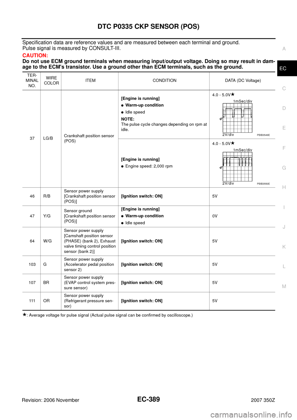
Specification data are reference values and are measured between each terminal and ground.
Pulse signal is measured by CONSULT-III.
CAUTION:
Do not use ECM ground terminals when measuring input/output voltage. Doing so may result in dam-
age to the ECM's transistor. Use a ground other than ECM terminals, such as the ground.
: Average voltage for pulse signal (Actual pulse signal can be confirmed by oscilloscope.)TER-
MINAL
NO.WIRE
COLORITEM CONDITION DATA (DC Voltage)
37 LG/BCrankshaft position sensor
(POS)[Engine is running]
�Warm-up condition
�Idle speed
NOTE:
The pulse cycle changes depending on rpm at
idle.4.0 - 5.0V
[Engine is running]
�Engine speed: 2,000 rpm4.0 - 5.0V
46 R/BSensor power supply
[Crankshaft position sensor
(POS)][Ignition switch: ON]5V
47 Y/GSensor ground
[Crankshaft position sensor
(POS)][Engine is running]
�Warm-up condition
�Idle speed0V
64 W/GSensor power supply
[Camshaft position sensor
(PHASE) (bank 2), Exhaust
valve timing control position
sensor (bank 2)][Ignition switch: ON]5V
103 GSensor power supply
(Accelerator pedal position
sensor 2)[Ignition switch: ON]5V
107 BRSensor power supply
(EVAP control system pres-
sure sensor)[Ignition switch: ON]5V
111 O RSensor power supply
(Refrigerant pressure sen-
sor)[Ignition switch: ON]5V
PBIB3549E
PBIB3550E
Page 390 of 720
EC-390
DTC P0335 CKP SENSOR (POS)
Revision: 2006 November2007 350Z
Diagnostic ProcedureNBS00089
1. CHECK GROUND CONNECTIONS
Models with VDC system, navigation system or telephone
1. Turn ignition switch OFF.
2. Loosen and retighten ground screws on the body. Refer to EC-150, "
Ground Inspection" .
Models without VDC system, navigation system and telephone
1. Turn ignition switch OFF.
2. Loosen and retighten ground screws on the body. Refer to EC-150, "
Ground Inspection" .
OK or NG
OK >> GO TO 2.
NG >> Repair or replace ground connections.
1. Body ground E17 2. Body ground E43 3. Body ground B102
:Vehicle front
1. Body ground E17 2. Body ground E43 3. Body ground F152
(Passenger side view with dash side
finisher removed)
:Vehicle front
PBIB3560E
PBIB3561E
Page 391 of 720
DTC P0335 CKP SENSOR (POS)
EC-391
C
D
E
F
G
H
I
J
K
L
MA
EC
Revision: 2006 November2007 350Z
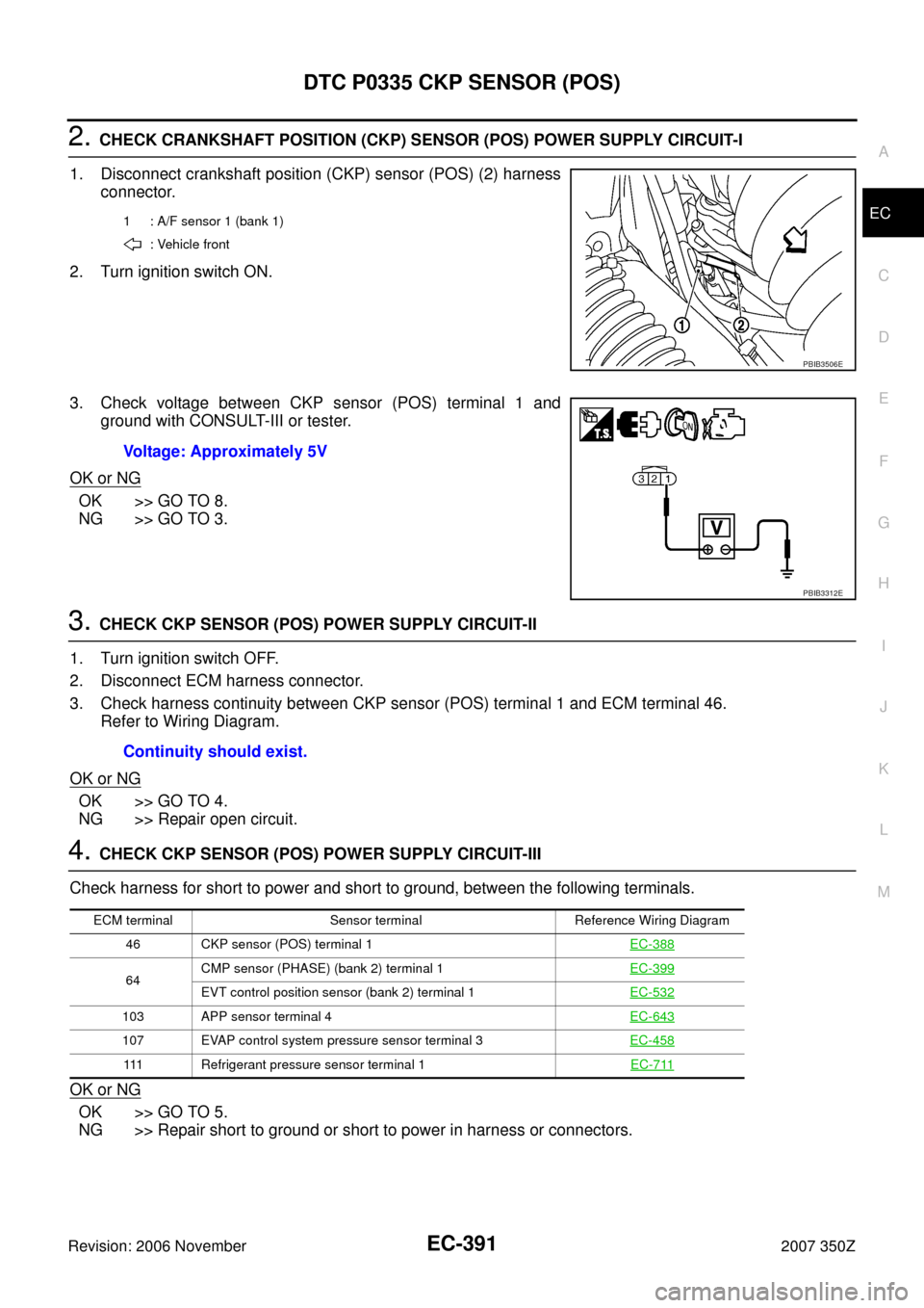
2. CHECK CRANKSHAFT POSITION (CKP) SENSOR (POS) POWER SUPPLY CIRCUIT-I
1. Disconnect crankshaft position (CKP) sensor (POS) (2) harness
connector.
2. Turn ignition switch ON.
3. Check voltage between CKP sensor (POS) terminal 1 and
ground with CONSULT-III or tester.
OK or NG
OK >> GO TO 8.
NG >> GO TO 3.
3. CHECK CKP SENSOR (POS) POWER SUPPLY CIRCUIT-II
1. Turn ignition switch OFF.
2. Disconnect ECM harness connector.
3. Check harness continuity between CKP sensor (POS) terminal 1 and ECM terminal 46.
Refer to Wiring Diagram.
OK or NG
OK >> GO TO 4.
NG >> Repair open circuit.
4. CHECK CKP SENSOR (POS) POWER SUPPLY CIRCUIT-III
Check harness for short to power and short to ground, between the following terminals.
OK or NG
OK >> GO TO 5.
NG >> Repair short to ground or short to power in harness or connectors.
1 : A/F sensor 1 (bank 1)
: Vehicle front
PBIB3506E
Voltage: Approximately 5V
PBIB3312E
Continuity should exist.
ECM terminal Sensor terminal Reference Wiring Diagram
46 CKP sensor (POS) terminal 1EC-388
64CMP sensor (PHASE) (bank 2) terminal 1EC-399EVT control position sensor (bank 2) terminal 1EC-532
103 APP sensor terminal 4EC-643
107 EVAP control system pressure sensor terminal 3EC-458
111 Refrigerant pressure sensor terminal 1EC-711
Page 392 of 720
EC-392
DTC P0335 CKP SENSOR (POS)
Revision: 2006 November2007 350Z
5. CHECK COMPONENTS
Check the following.
�Camshaft position sensor (PHASE) (bank 2) (Refer to EC-405, "Component Inspection" .)
�Exhaust valve timing control position sensor (bank 2) (Refer to EC-539, "Component Inspection" .)
�EVAP control system pressure sensor (Refer to EC-464, "Component Inspection" .)
�Refrigerant pressure sensor (Refer to AT C - 8 0 , "COMPONENT INSPECTION" .)
OK or NG
OK >> GO TO 6.
NG >> Replace malfunctioning component.
6. CHECK APP SENSOR
Refer to EC-648, "
Component Inspection" .
OK or NG
OK >> GO TO 12.
NG >> GO TO 7.
7. REPLACE ACCELERATOR PEDAL ASSEMBLY
1. Replace accelerator pedal assembly.
2. Perform EC-77, "
Accelerator Pedal Released Position Learning" .
3. Perform EC-77, "
Throttle Valve Closed Position Learning" .
4. Perform EC-77, "
Idle Air Volume Learning" .
>>INSPECTION END
8. CHECK CKP SENSOR (POS) GROUND CIRCUIT FOR OPEN AND SHORT
1. Turn ignition switch OFF.
2. Disconnect ECM harness connector.
3. Check the continuity between CKP sensor (POS) terminal 2 and ECM terminal 47.
Refer to Wiring Diagram.
4. Also check harness for short to ground short to power.
OK or NG
OK >> GO TO 9.
NG >> Repair open circuit or short to ground or short to power in harness connectors.
9. CHECK CKP SENSOR (POS) INPUT SIGNAL CIRCUIT FOR OPEN AND SHORT
1. Check the continuity between CKP sensor (POS) terminal 3 and ECM terminal 37.
Refer to Wiring Diagram.
2. Also check harness for short to ground and short to power.
OK or NG
OK >> GO TO 10.
NG >> Repair open circuit or short to ground or short to power in harness or connectors.Continuity should exist.
Continuity should exist.
Page 393 of 720
DTC P0335 CKP SENSOR (POS)
EC-393
C
D
E
F
G
H
I
J
K
L
MA
EC
Revision: 2006 November2007 350Z
10. CHECK CRANKSHAFT POSITION SENSOR (POS)
Refer to EC-393, "
Component Inspection" .
OK or NG
OK >> GO TO 11.
NG >> Replace CKP sensor (POS).
11 . CHECK GEAR TOOTH
Visually check for chipping signal plate gear tooth.
OK or NG
OK >> GO TO 12.
NG >> Replace the signal plate.
12. CHECK INTERMITTENT INCIDENT
Refer to EC-141, "
TROUBLE DIAGNOSIS FOR INTERMITTENT INCIDENT" .
>>INSPECTION END
Component InspectionNBS0008A
CRANKSHAFT POSITION SENSOR (POS)
1. Loosen the fixing bolt of the sensor.
2. Disconnect CKP sensor (POS) harness connector.
3. Remove the sensor.
4. Visually check the sensor for chipping.
5. Check resistance as shown in the figure.
Removal and InstallationNBS0008B
CRANKSHAFT POSITION SENSOR (POS)
Refer to EM-26, "OIL PAN AND OIL STRAINER" .
PBIB3564E
Terminal No. (Polarity) Resistance Ω [at 25°C (77°F)]
1 (+) - 2 (-)
Except 0 or ∞ 1 (+) - 3 (-)
2 (+) - 3 (-)
PBIA9584J
Page 394 of 720
EC-394
DTC P0340, P0345 CMP SENSOR (PHASE)
Revision: 2006 November2007 350Z
DTC P0340, P0345 CMP SENSOR (PHASE)PFP:23731
Component DescriptionNBS0008C
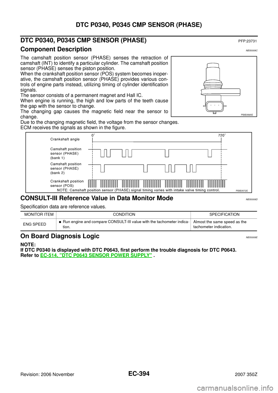
The camshaft position sensor (PHASE) senses the retraction of
camshaft (INT) to identify a particular cylinder. The camshaft position
sensor (PHASE) senses the piston position.
When the crankshaft position sensor (POS) system becomes inoper-
ative, the camshaft position sensor (PHASE) provides various con-
trols of engine parts instead, utilizing timing of cylinder identification
signals.
The sensor consists of a permanent magnet and Hall IC.
When engine is running, the high and low parts of the teeth cause
the gap with the sensor to change.
The changing gap causes the magnetic field near the sensor to
change.
Due to the changing magnetic field, the voltage from the sensor changes.
ECM receives the signals as shown in the figure.
CONSULT-III Reference Value in Data Monitor ModeNBS0008D
Specification data are reference values.
On Board Diagnosis LogicNBS0008E
NOTE:
If DTC P0340 is displayed with DTC P0643, first perform the trouble diagnosis for DTC P0643.
Refer to EC-514, "
DTC P0643 SENSOR POWER SUPPLY" .
PBIB3565E
PBIB3572E
MONITOR ITEM CONDITION SPECIFICATION
ENG SPEED
�Run engine and compare CONSULT-III value with the tachometer indica-
tion.Almost the same speed as the
tachometer indication.
Page 395 of 720
DTC P0340, P0345 CMP SENSOR (PHASE)
EC-395
C
D
E
F
G
H
I
J
K
L
MA
EC
Revision: 2006 November2007 350Z
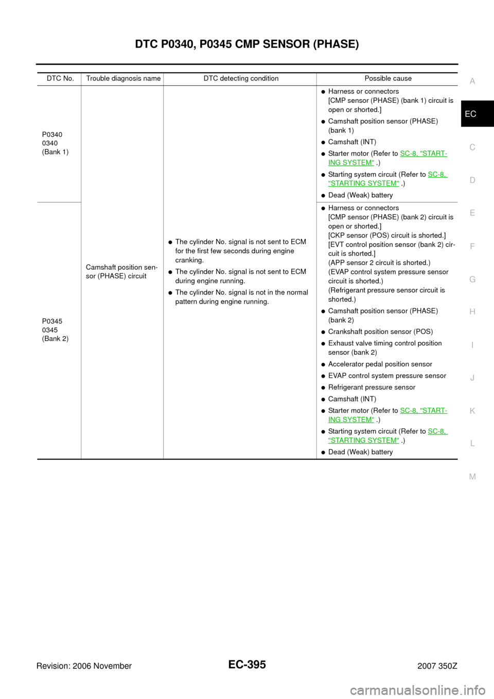
DTC No. Trouble diagnosis name DTC detecting condition Possible cause
P0340
0340
(Bank 1)
Camshaft position sen-
sor (PHASE) circuit
�The cylinder No. signal is not sent to ECM
for the first few seconds during engine
cranking.
�The cylinder No. signal is not sent to ECM
during engine running.
�The cylinder No. signal is not in the normal
pattern during engine running.
�Harness or connectors
[CMP sensor (PHASE) (bank 1) circuit is
open or shorted.]
�Camshaft position sensor (PHASE)
(bank 1)
�Camshaft (INT)
�Starter motor (Refer to SC-8, "START-
ING SYSTEM" .)
�Starting system circuit (Refer to SC-8,
"STARTING SYSTEM" .)
�Dead (Weak) battery
P0345
0345
(Bank 2)
�Harness or connectors
[CMP sensor (PHASE) (bank 2) circuit is
open or shorted.]
[CKP sensor (POS) circuit is shorted.]
[EVT control position sensor (bank 2) cir-
cuit is shorted.]
(APP sensor 2 circuit is shorted.)
(EVAP control system pressure sensor
circuit is shorted.)
(Refrigerant pressure sensor circuit is
shorted.)
�Camshaft position sensor (PHASE)
(bank 2)
�Crankshaft position sensor (POS)
�Exhaust valve timing control position
sensor (bank 2)
�Accelerator pedal position sensor
�EVAP control system pressure sensor
�Refrigerant pressure sensor
�Camshaft (INT)
�Starter motor (Refer to SC-8, "START-
ING SYSTEM" .)
�Starting system circuit (Refer to SC-8,
"STARTING SYSTEM" .)
�Dead (Weak) battery