Page 5 of 92

COMBINATION METERS
DI-5
C
D
E
F
G
H
I
J
L
MA
B
DI
Revision: 2006 November2007 350Z
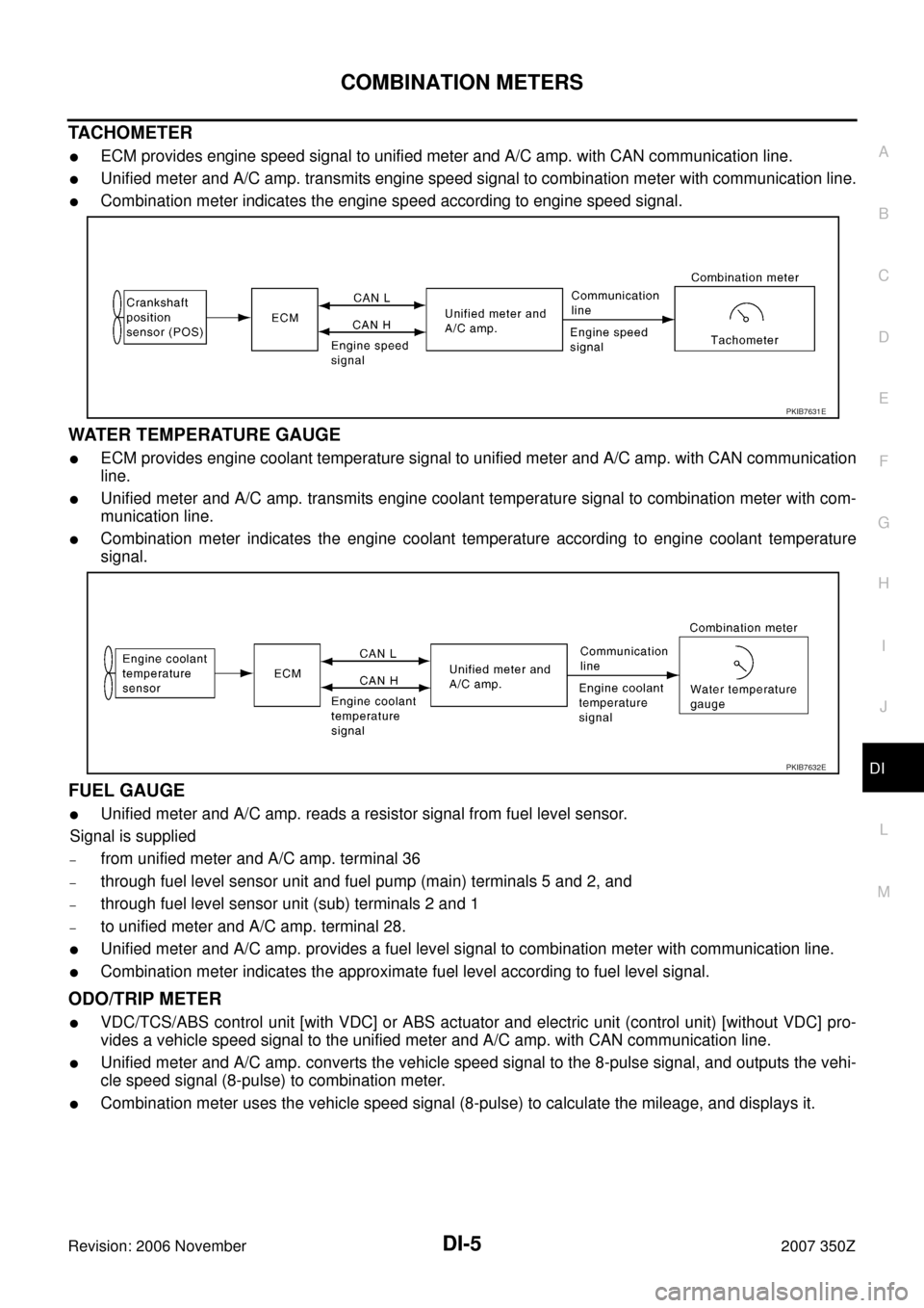
TACHOMETER
�ECM provides engine speed signal to unified meter and A/C amp. with CAN communication line.
�Unified meter and A/C amp. transmits engine speed signal to combination meter with communication line.
�Combination meter indicates the engine speed according to engine speed signal.
WATER TEMPERATURE GAUGE
�ECM provides engine coolant temperature signal to unified meter and A/C amp. with CAN communication
line.
�Unified meter and A/C amp. transmits engine coolant temperature signal to combination meter with com-
munication line.
�Combination meter indicates the engine coolant temperature according to engine coolant temperature
signal.
FUEL GAUGE
�Unified meter and A/C amp. reads a resistor signal from fuel level sensor.
Signal is supplied
–from unified meter and A/C amp. terminal 36
–through fuel level sensor unit and fuel pump (main) terminals 5 and 2, and
–through fuel level sensor unit (sub) terminals 2 and 1
–to unified meter and A/C amp. terminal 28.
�Unified meter and A/C amp. provides a fuel level signal to combination meter with communication line.
�Combination meter indicates the approximate fuel level according to fuel level signal.
ODO/TRIP METER
�VDC/TCS/ABS control unit [with VDC] or ABS actuator and electric unit (control unit) [without VDC] pro-
vides a vehicle speed signal to the unified meter and A/C amp. with CAN communication line.
�Unified meter and A/C amp. converts the vehicle speed signal to the 8-pulse signal, and outputs the vehi-
cle speed signal (8-pulse) to combination meter.
�Combination meter uses the vehicle speed signal (8-pulse) to calculate the mileage, and displays it.
PKIB7631E
PKIB7632E
Page 21 of 92

COMBINATION METERS
DI-21
C
D
E
F
G
H
I
J
L
MA
B
DI
Revision: 2006 November2007 350Z
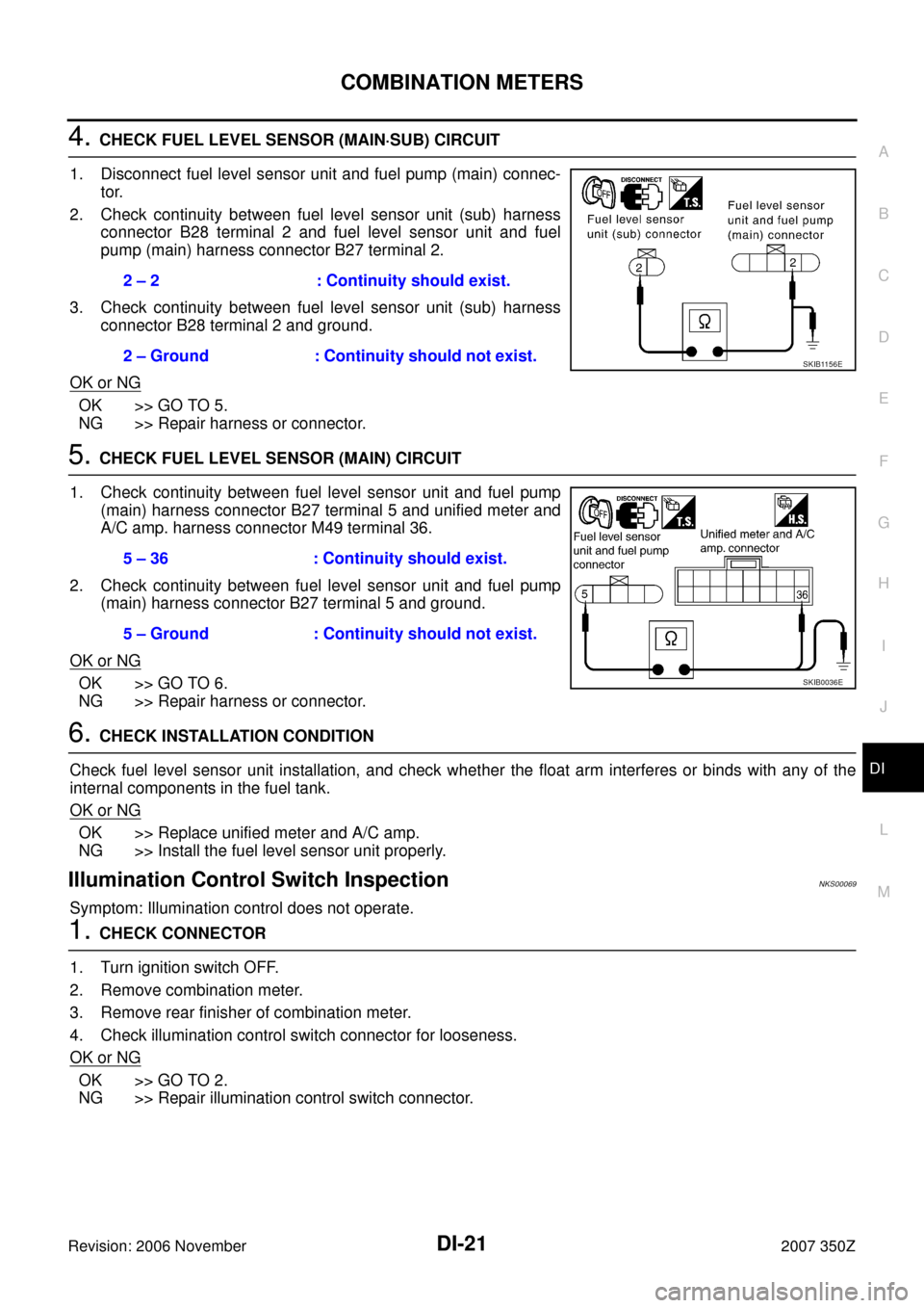
4. CHECK FUEL LEVEL SENSOR (MAIN·SUB) CIRCUIT
1. Disconnect fuel level sensor unit and fuel pump (main) connec-
tor.
2. Check continuity between fuel level sensor unit (sub) harness
connector B28 terminal 2 and fuel level sensor unit and fuel
pump (main) harness connector B27 terminal 2.
3. Check continuity between fuel level sensor unit (sub) harness
connector B28 terminal 2 and ground.
OK or NG
OK >> GO TO 5.
NG >> Repair harness or connector.
5. CHECK FUEL LEVEL SENSOR (MAIN) CIRCUIT
1. Check continuity between fuel level sensor unit and fuel pump
(main) harness connector B27 terminal 5 and unified meter and
A/C amp. harness connector M49 terminal 36.
2. Check continuity between fuel level sensor unit and fuel pump
(main) harness connector B27 terminal 5 and ground.
OK or NG
OK >> GO TO 6.
NG >> Repair harness or connector.
6. CHECK INSTALLATION CONDITION
Check fuel level sensor unit installation, and check whether the float arm interferes or binds with any of the
internal components in the fuel tank.
OK or NG
OK >> Replace unified meter and A/C amp.
NG >> Install the fuel level sensor unit properly.
Illumination Control Switch InspectionNKS00069
Symptom: Illumination control does not operate.
1. CHECK CONNECTOR
1. Turn ignition switch OFF.
2. Remove combination meter.
3. Remove rear finisher of combination meter.
4. Check illumination control switch connector for looseness.
OK or NG
OK >> GO TO 2.
NG >> Repair illumination control switch connector.2 – 2 : Continuity should exist.
2 – Ground : Continuity should not exist.
SKIB1156E
5 – 36 : Continuity should exist.
5 – Ground : Continuity should not exist.
SKIB0036E
Page 23 of 92

COMBINATION METERS
DI-23
C
D
E
F
G
H
I
J
L
MA
B
DI
Revision: 2006 November2007 350Z
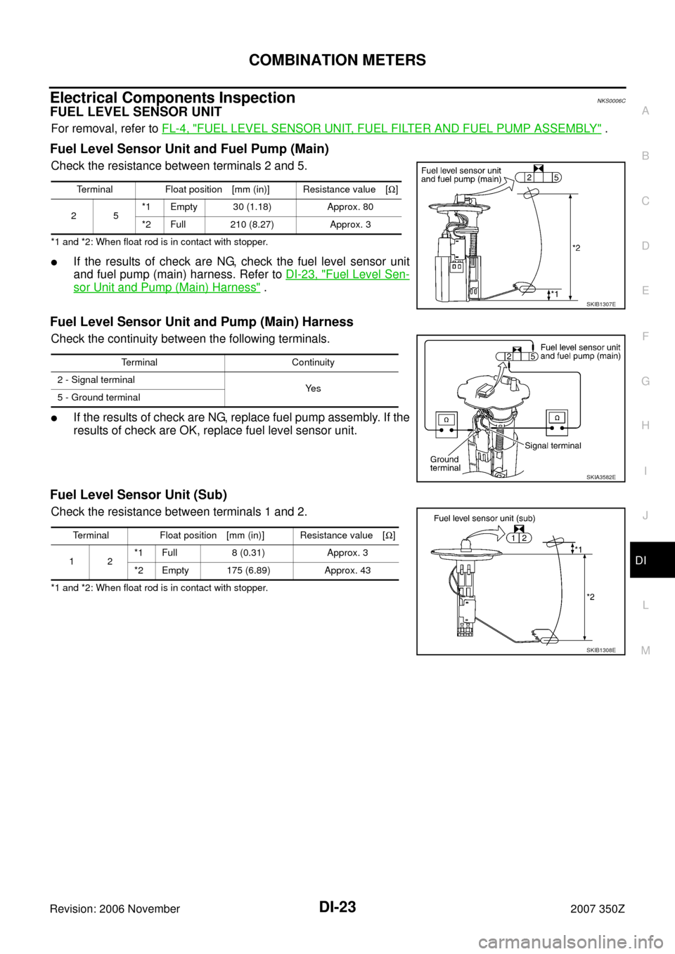
Electrical Components InspectionNKS0006C
FUEL LEVEL SENSOR UNIT
For removal, refer to FL-4, "FUEL LEVEL SENSOR UNIT, FUEL FILTER AND FUEL PUMP ASSEMBLY" .
Fuel Level Sensor Unit and Fuel Pump (Main)
Check the resistance between terminals 2 and 5.
*1 and *2: When float rod is in contact with stopper.
�If the results of check are NG, check the fuel level sensor unit
and fuel pump (main) harness. Refer to DI-23, "
Fuel Level Sen-
sor Unit and Pump (Main) Harness" .
Fuel Level Sensor Unit and Pump (Main) Harness
Check the continuity between the following terminals.
�If the results of check are NG, replace fuel pump assembly. If the
results of check are OK, replace fuel level sensor unit.
Fuel Level Sensor Unit (Sub)
Check the resistance between terminals 1 and 2.
*1 and *2: When float rod is in contact with stopper.Terminal Float position [mm (in)] Resistance value [Ω]
25*1 Empty 30 (1.18) Approx. 80
*2 Full 210 (8.27) Approx. 3
SKIB1307E
Terminal Continuity
2 - Signal terminal
Ye s
5 - Ground terminal
SKIA3582E
Terminal Float position [mm (in)] Resistance value [Ω]
12*1 Full 8 (0.31) Approx. 3
*2 Empty 175 (6.89) Approx. 43
SKIB1308E