BRAKE PEDAL
BR-7
C
D
E
G
H
I
J
K
L
MA
B
BR
Revision: 2006 November2007 350Z
BRAKE PEDALPFP:46501
Inspection and AdjustmentNFS00006
PLAY AND CLEARANCE BETWEEN THE BRAKE PEDAL AND FLOOR PANEL WITH PEDAL
DEPRESSED
1. Check the brake pedal free height from the dash lower panel (1).
2. Adjust the height referring to the following specifications.
ADJUSTMENT
1. Loosen the stop lamp switch and ASCD cancel switch by rotat-
ing it counterclockwise by 45°.
2. Loosen the lock nut (A) on the input rod, then rotate the input
rod to set the pedal to the specified height, and tighten the lock
nut (A) to the specified torque. Refer to BR-23, "
Components" .
CAUTION:
Check that the threaded end of the input rod stays inside
the clevis.
3. With the pedal pulled and held by hand, press the stop lamp
switch and ASCD cancel switch until its threaded end contacts
the stopper rubber.
4. With the threaded end of the stop lamp switch contacting the
stopper rubber and ASCD cancel switch, rotate the switch clock-
wise by 45° to secure.
CAUTION:
Make sure that the clearance “C” between the stopper rub-
ber and threaded end of the stop lamp switch and ASCD
cancel switch is within the standard.
5. Check the pedal play.
CAUTION:
Make sure that the stop lamps go off when the pedal is
released.
6. Start the engine to check the brake pedal's depressed height.Brake pedal height “H
1 ” (from dash lower panel top sur-
face)
M/T models : 153.2 – 163.2 mm (6.03 – 6.43 in)
A/T models : 161.5 – 171.5 mm (6.36 – 6.75 in)
Depressed pedal height “H
2 ” [under a force of 490 N (50
kg, 110 lb) with the engine running]
M/T models : More than 90 mm (3.54 in)
A/T models : More than 95 mm (3.74 in)
Clearance “C ” between threaded end of the stop lamp
switch/ASCD cancel switch (2) and stopper rubber (3).
: 0.74 – 1.96 mm (0.0291 – 0.0772 in)
Pedal play “A” : 3 – 11 mm (0.12 – 0.43 in)
PFIA0877E
PFIA0819E
BR-12
BRAKE TUBE AND HOSE
Revision: 2006 November2007 350Z
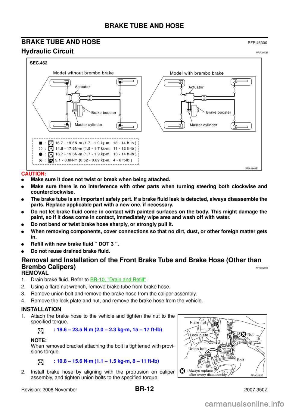
BRAKE TUBE AND HOSEPFP:46300
Hydraulic CircuitNFS0000B
CAUTION:
�Make sure it does not twist or break when being attached.
�Make sure there is no interference with other parts when turning steering both clockwise and
counterclockwise.
�The brake tube is an important safety part. If a brake fluid leak is detected, always disassemble the
parts. Replace applicable part with a new one, if necessary.
�Do not let brake fluid come in contact with painted surfaces on the body. This might damage the
paint, so if it does come in contact, immediately wipe area and wash off with water.
�Do not bend or twist brake hose sharply, or strongly pull it.
�When removing components, cover connections so that no dirt, dust, or other foreign matter gets
in.
�Refill with new brake fluid “ DOT 3 ”.
�Do not reuse drained brake fluid.
Removal and Installation of the Front Brake Tube and Brake Hose (Other than
Brembo Calipers)
NFS0000C
REMOVAL
1. Drain brake fluid. Refer to BR-10, "Drain and Refill" .
2. Using a flare nut wrench, remove brake tube from brake hose.
3. Remove union bolt and remove the brake hose from the caliper assembly.
4. Remove the lock plate and nut, and remove the brake hose from the vehicle.
INSTALLATION
1. Attach the brake hose to the vehicle and tighten the nut to the
specified torque.
NOTE:
When removed bracket attaching the bolt is tightened with provi-
sions torque.
2. Install brake hose by aligning with the protrusion on caliper
assembly, and tighten union bolts to the specified torque.
SFIA1869E
: 19.6 – 23.5 N·m (2.0 – 2.3 kg-m, 15 – 17 ft-lb)
: 10.8 – 15.6 N·m (1.1 – 1.5 kg-m, 8 – 11 ft-lb)
PFIA0230E