BR-24
BRAKE BOOSTER
Revision: 2006 November2007 350Z
Removal and InstallationNFS0000M
REMOVAL
CAUTION:
�Be careful not to deform or bend brake piping while removing and installing the brake booster.
�Replace clevis pin if it is damaged.
�Be careful not to damage brake booster stud bolt threads. If brake booster is tilted or inclined dur-
ing installation, the dash panel may damage the threads.
�Attach the check valve in the correct orientation.
1. Remove vacuum hose from the brake booster. Refer to BR-25, "
VACUUM LINES" .
2. Remove the brake master cylinder. Refer to BR-24, "
Removal and Installation" .
3. Remove the brake piping between brake master cylinder and ABS actuator and electric unit (control unit).
Refer to BR-12, "
Hydraulic Circuit" .
CAUTION:
For M/T vehicles with remove the brake piping after removing the clutch reservoir tank bolt.
4. Remove the brake pedal attachment snap pin and clevis pin from inside the vehicle.
5. Remove the nuts on the brake booster and brake pedal assembly.
6. Remove brake booster assembly from the engine compartment side.
INSPECTION AFTER REMOVAL
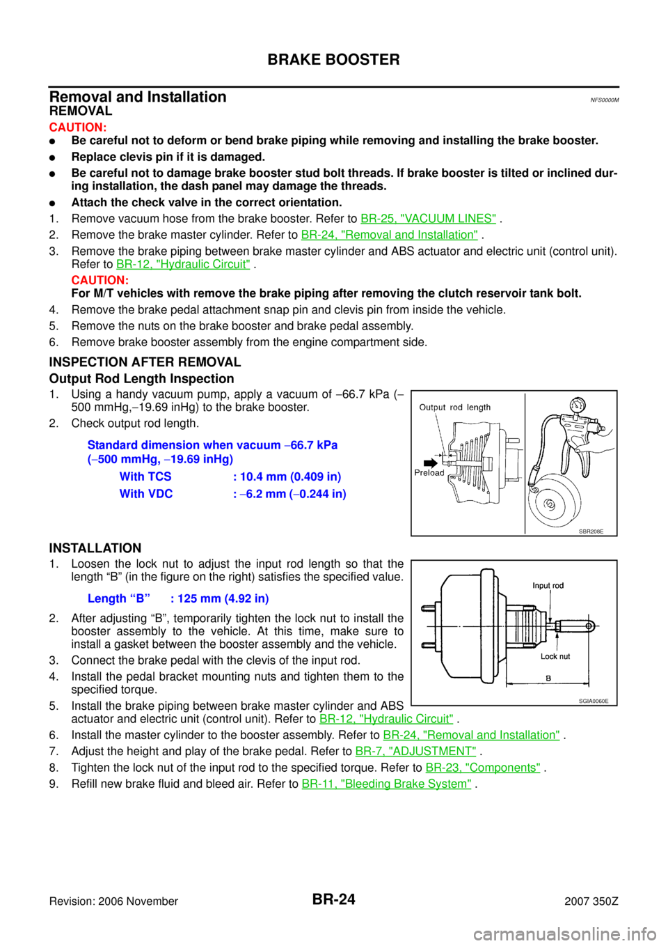
Output Rod Length Inspection
1. Using a handy vacuum pump, apply a vacuum of −66.7 kPa (−
500 mmHg,−19.69 inHg) to the brake booster.
2. Check output rod length.
INSTALLATION
1. Loosen the lock nut to adjust the input rod length so that the
length “B” (in the figure on the right) satisfies the specified value.
2. After adjusting “B”, temporarily tighten the lock nut to install the
booster assembly to the vehicle. At this time, make sure to
install a gasket between the booster assembly and the vehicle.
3. Connect the brake pedal with the clevis of the input rod.
4. Install the pedal bracket mounting nuts and tighten them to the
specified torque.
5. Install the brake piping between brake master cylinder and ABS
actuator and electric unit (control unit). Refer to BR-12, "
Hydraulic Circuit" .
6. Install the master cylinder to the booster assembly. Refer to BR-24, "
Removal and Installation" .
7. Adjust the height and play of the brake pedal. Refer to BR-7, "
ADJUSTMENT" .
8. Tighten the lock nut of the input rod to the specified torque. Refer to BR-23, "
Components" .
9. Refill new brake fluid and bleed air. Refer to BR-11, "
Bleeding Brake System" . Standard dimension when vacuum −66.7 kPa
(−500 mmHg, −19.69 inHg)
With TCS : 10.4 mm (0.409 in)
With VDC : −6.2 mm (−0.244 in)
SBR208E
Length “B” : 125 mm (4.92 in)
SGIA0060E
BR-52
SERVICE DATA AND SPECIFICATIONS (SDS)
Revision: 2006 November2007 350Z
SERVICE DATA AND SPECIFICATIONS (SDS)PFP:00030
General SpecificationsNFS00019
Unit: mm (in)
Brake PedalNFS0001A
Brake BoosterNFS0001B
Check ValveNFS0001C
Front Disc BrakeNFS0001D
Brake model Other than brembo With brembo
Front brakeRotor outer diameter × thickness 320 × 28.0 (12.60 × 1.102) 324 × 30.0 (12.76 × 1.181)
Pad length × width × thickness130.0 × 50.0 × 11.0
(5.12 × 1.97 × 0.43)11 7 . 1 × 53.3 × 9.3
(4.61 × 2.098 × 0.366)
Cylinder bore diameter 45.0 × 2 (1.772 × 2) 38 (1.50) × 2 + 44 (1.73) × 2
Rear brake Rotor outer diameter × thickness 308 × 16 (12.13 × 0.63) 322 × 22 (12.68 × 0.87)
Pad length × width × thickness83.0 × 31.9 × 8.5
(3.27 × 1.26 × 0.335)76.6 × 45 × 9.1
(3.016 × 1.77 × 0.358)
Cylinder bore diameter 42.86 (1.6874) 40.0 × 2 (1.575)
Master cylinder Cylinder bore diameter 26.99 (1.0626)
Control valve Valve type Electric brake force distribution
Brake booster Diaphragm diameterCoupe 255 (10.04)Pri: 230 (9.06)
Sec: 205 (8.07)
RoadsterPri: 230 (9.06)
Sec: 205 (8.07)Pri: 230 (9.06)
Sec: 205 (8.07)
Recommended brake fluid DOT 3
Brake pedal height (from dash lower panel top surface)M/T models 153.2 – 163.2 mm (6.03 – 6.43 in)
A/T models 161.5 – 171.5 mm (6.36 – 6.75 in)
Depressed pedal height [under a force of 490 N (50 kg, 110 lb)
with the engine running]M/T models More than 90 mm (3.54 in)
A/T models More than 95 mm (3.74 in)
Clearance between threaded end of the stop lamp switch/ASCD cancel switch and
stopper rubber0.74 – 1.96 mm (0.0291 – 0.0772 in)
Pedal play3 – 11 mm (0.12 – 0.43 in)
Vacuum leakage
[at vacuum of −66.7 kPa (−500 mmHg, −19.69 inHg)]Within 3.3 kPa (25 mmHg, 0.98 inHg) of vacuum for 15 seconds
Output rod lengthWith TCS 10.4 mm (0.409 in)
With VDC−6.2 mm (−0.244 in)
Input rod length125 mm (4.92 in)
Vacuum leakage
[at vacuum of −66.7 kPa(−500 mmHg, −19.69 inHg)]Within 1.3 kPa (10 mmHg, 0.39 inHg) of vacuum for 15 seconds
Brake model Other than brembo With brembo
Brake padStandard thickness (new) 11.0 mm (0.433 in) 9.3 mm (0.366 in)
Repair limit thickness 2.0 mm (0.079 in) 2.0 mm (0.079 in)
Disc rotorStandard thickness (new) 28.0 mm (1.102 in) 30.0mm (1.181 in)
Repair limit thickness 26.0 mm (1.024 in) 28.4mm (1.118 in)
Maximum uneven wear (measured at 8 positions) 0.015mm (0.0006 in) or less 0.015 mm (0.0006 in) or less
Runout limit (with it attached to the vehicle) 0.035 mm (0.0014 in) or less 0.040 mm (0.0016 in) or less
Runout limit (just the disc rotor) 0.020 mm (0.0008 in) or less 0.040 mm (0.0016 in) or less

Revision: 2006 November2007 350Z
SERVICE DATA AND SPECIFICATIONS (SDS)PFP:00030
General SpecificationsNFS00019
Unit: mm (in)
Brake PedalNFS0001A
Brake Boost")