Page 260 of 312
AT-260
DISASSEMBLY
Revision: 2006 November2007 350Z
24. Remove high and low reverse clutch assembly from direct clutch
assembly.
CAUTION:
Make sure that needle bearing is installed to high and low
reverse clutch assembly edge surface.
25. Remove direct clutch assembly from reverse brake.
26. Remove needle bearing from drum support.
27. Remove snap ring from A/T assembly harness connector.
28. Push A/T assembly harness connector.
CAUTION:
Be careful not to damage connector.
SCIA2306E
SCIA5019E
SCIA5198E
SCIA5021E
SCIA5022E
Page 265 of 312
DISASSEMBLY
AT-265
D
E
F
G
H
I
J
K
L
MA
B
AT
Revision: 2006 November2007 350Z
50. Remove seal rings from output shaft.
51. Remove needle bearing from transmission case.
52. Remove revolution sensor from transmission case.
CAUTION:
�Do not subject it to impact by dropping or hitting it.
�Do not disassemble.
�Do not allow metal filings, etc. to get on the sensor's front
edge magnetic area.
�Do not place in an area affected by magnetism.
53. Remove reverse brake snap ring (fixing plate) using 2 flat-
bladed screwdrivers.
NOTE:
Press out snap ring from transmission case oil pan side gap
using a flat-bladed screwdriver, and remove it using another
screwdriver.
54. Remove reverse brake retaining plate from transmission case.
�Check facing for burns, cracks or damage. If necessary,
replace the plate.
55. Remove N-spring from transmission case.
SCIA5209E
SCIA5031E
SCIA2320E
SCIA5032E
SCIA5214E
Page 266 of 312
AT-266
DISASSEMBLY
Revision: 2006 November2007 350Z
56. Remove reverse brake drive plates, driven plates and dish
plates from transmission case.
CAUTION:
Be careful to remove it with N-spring.
57. Remove snap ring (fixing spring retainer) using a flat-bladed
screwdriver.
58. Remove spring retainer and return spring from transmission
case.
59. Remove seal rings from drum support.
60. Remove needle bearing from drum support edge surface.
SCIA2322E
SCIA2323E
SCIA2324E
SCIA3333E
SCIA2796E
Page 267 of 312
DISASSEMBLY
AT-267
D
E
F
G
H
I
J
K
L
MA
B
AT
Revision: 2006 November2007 350Z
61. Remove reverse brake piston from transmission case with com-
pressed air. Refer to AT- 2 5 2 , "
Oil Channel" .
CAUTION:
Care should be taken not to abruptly blow air. It makes pis-
tons incline, as the result, it becomes hard to disassemble
the pistons.
62. Remove D-rings from reverse brake piston.
63. Use a pin punch [4 mm (0.16 in) dia. commercial service tool] to
knock out retaining pin.
64. Remove manual shaft retaining pin using pair of nippers.
SCIA5047E
SCIA6330E
SCIA2328E
SCIA2329E
Page 281 of 312
REPAIR FOR COMPONENT PARTS
AT-281
D
E
F
G
H
I
J
K
L
MA
B
AT
Revision: 2006 November2007 350Z
Mid Sun Gear, Rear Sun Gear, High and Low Reverse Clutch HubNCS0009F
COMPONENTS
DISASSEMBLY
1. Remove needle bearing and bearing race from high and low
reverse clutch hub.
2. Remove snap ring from mid sun gear assembly using pair of
snap ring pliers.
CAUTION:
Do not expand snap ring excessively.
1. Needle bearing 2. Bearing race 3. Snap ring
4. High and low reverse clutch hub 5. Needle bearing 6. Snap ring
7. 1st one-way clutch 8. Rear sun gear 9. Seal ring
10. Mid sun gear
SCIA2851E
SCIA2854E
SCIA2855E
Page 282 of 312
AT-282
REPAIR FOR COMPONENT PARTS
Revision: 2006 November2007 350Z
3. Remove high and low reverse clutch hub from mid sun gear
assembly.
a. Remove needle bearing from high and low reverse clutch hub.
4. Remove rear sun gear assembly (1) from mid sun gear assem-
bly.
a. Remove snap ring from rear sun gear using a flat-bladed screw-
driver.
SCIA2856E
SCIA2857E
SCIA8155E
SCIA2859E
Page 283 of 312
REPAIR FOR COMPONENT PARTS
AT-283
D
E
F
G
H
I
J
K
L
MA
B
AT
Revision: 2006 November2007 350Z
b. Remove 1st one-way clutch from rear sun gear.
5. Remove seal rings from mid sun gear.
INSPECTION
High and Low Reverse Clutch Hub Snap Ring, Rear Sun Gear Snap Ring
�Check for deformation, fatigue or damage.
CAUTION:
If necessary, replace snap ring.
1st One-way Clutch
�Check frictional surface for wear or damage.
CAUTION:
If necessary, replace 1st one-way clutch.
Mid Sun Gear
�Check for deformation, fatigue or damage.
CAUTION:
If necessary, replace mid sun gear.
Rear Sun Gear
�Check for deformation, fatigue or damage.
CAUTION:
If necessary, replace rear sun gear.
High and Low Reverse Clutch Hub
�Check for deformation, fatigue or damage.
CAUTION:
If necessary, replace high and low reverse clutch hub.
SCIA4633E
SCIA2861E
Page 285 of 312

REPAIR FOR COMPONENT PARTS
AT-285
D
E
F
G
H
I
J
K
L
MA
B
AT
Revision: 2006 November2007 350Z
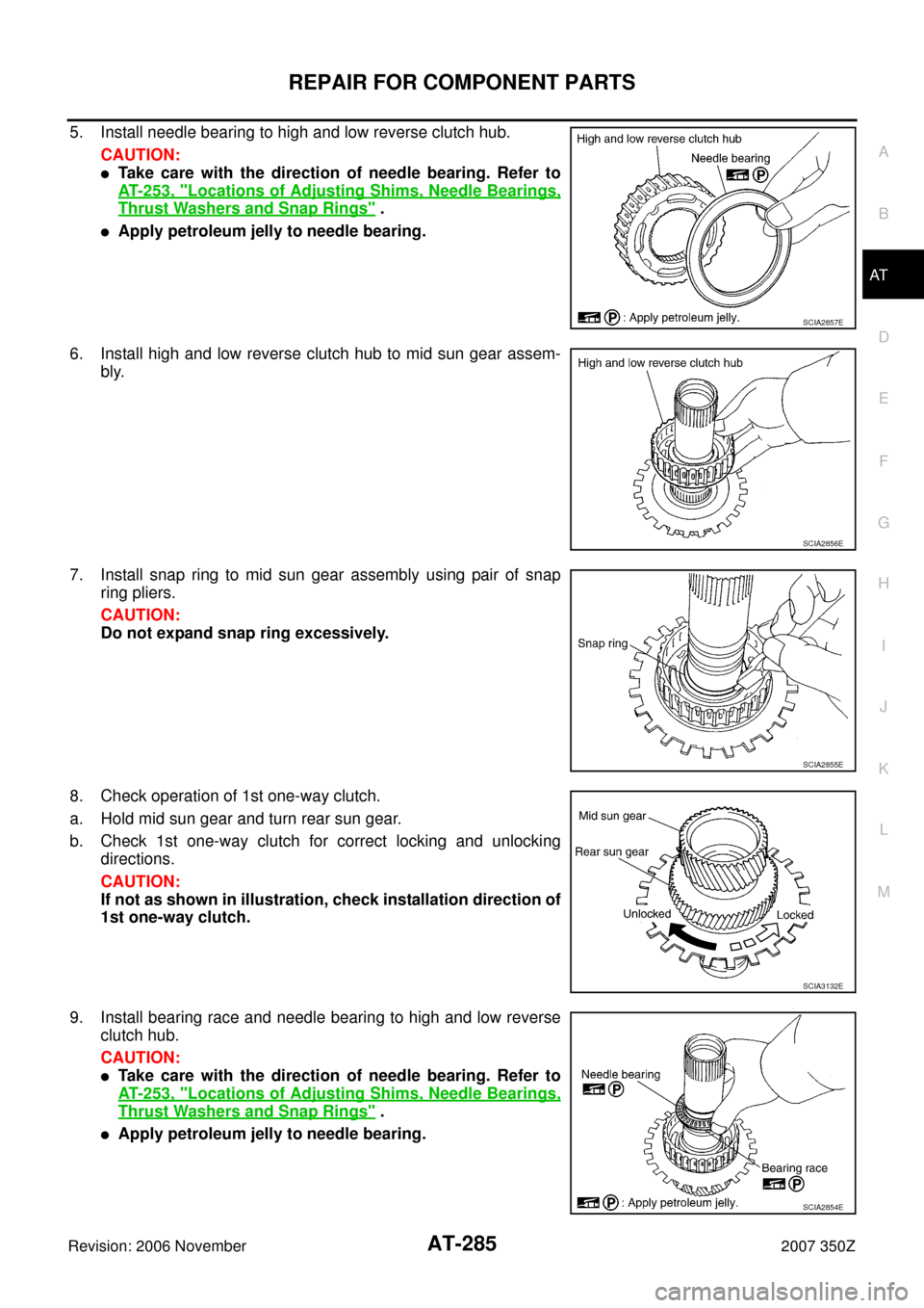
5. Install needle bearing to high and low reverse clutch hub.
CAUTION:
�Take care with the direction of needle bearing. Refer to
AT- 2 5 3 , "
Locations of Adjusting Shims, Needle Bearings,
Thrust Washers and Snap Rings" .
�Apply petroleum jelly to needle bearing.
6. Install high and low reverse clutch hub to mid sun gear assem-
bly.
7. Install snap ring to mid sun gear assembly using pair of snap
ring pliers.
CAUTION:
Do not expand snap ring excessively.
8. Check operation of 1st one-way clutch.
a. Hold mid sun gear and turn rear sun gear.
b. Check 1st one-way clutch for correct locking and unlocking
directions.
CAUTION:
If not as shown in illustration, check installation direction of
1st one-way clutch.
9. Install bearing race and needle bearing to high and low reverse
clutch hub.
CAUTION:
�Take care with the direction of needle bearing. Refer to
AT- 2 5 3 , "
Locations of Adjusting Shims, Needle Bearings,
Thrust Washers and Snap Rings" .
�Apply petroleum jelly to needle bearing.
SCIA2857E
SCIA2856E
SCIA2855E
SCIA3132E
SCIA2854E