Page 177 of 312
TROUBLE DIAGNOSIS FOR SYMPTOMS
AT-177
D
E
F
G
H
I
J
K
L
MA
B
AT
Revision: 2006 November2007 350Z
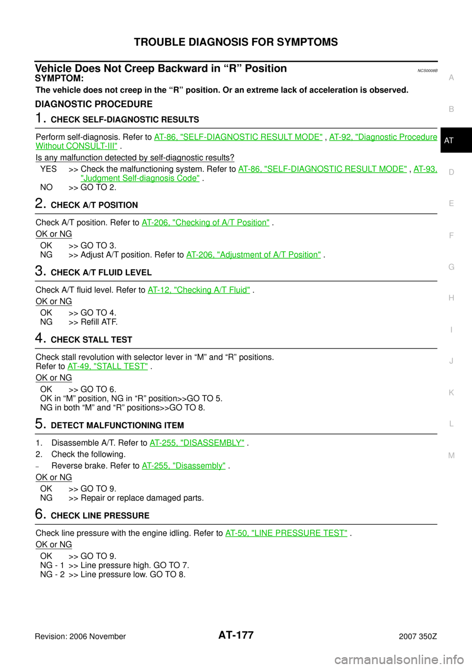
Vehicle Does Not Creep Backward in “R” PositionNCS0008B
SYMPTOM:
The vehicle does not creep in the “R” position. Or an extreme lack of acceleration is observed.
DIAGNOSTIC PROCEDURE
1. CHECK SELF-DIAGNOSTIC RESULTS
Perform self-diagnosis. Refer to AT- 8 6 , "
SELF-DIAGNOSTIC RESULT MODE" , AT- 9 2 , "Diagnostic Procedure
Without CONSULT-III" .
Is any malfunction detected by self-diagnostic results?
YES >> Check the malfunctioning system. Refer to AT- 8 6 , "SELF-DIAGNOSTIC RESULT MODE" , AT- 9 3 ,
"Judgment Self-diagnosis Code" .
NO >> GO TO 2.
2. CHECK A/T POSITION
Check A/T position. Refer to AT- 2 0 6 , "
Checking of A/T Position" .
OK or NG
OK >> GO TO 3.
NG >> Adjust A/T position. Refer to AT- 2 0 6 , "
Adjustment of A/T Position" .
3. CHECK A/T FLUID LEVEL
Check A/T fluid level. Refer to AT- 1 2 , "
Checking A/T Fluid" .
OK or NG
OK >> GO TO 4.
NG >> Refill ATF.
4. CHECK STALL TEST
Check stall revolution with selector lever in “M” and “R” positions.
Refer to AT- 4 9 , "
STALL TEST" .
OK or NG
OK >> GO TO 6.
OK in “M” position, NG in “R” position>>GO TO 5.
NG in both “M” and “R” positions>>GO TO 8.
5. DETECT MALFUNCTIONING ITEM
1. Disassemble A/T. Refer to AT- 2 5 5 , "
DISASSEMBLY" .
2. Check the following.
–Reverse brake. Refer to AT- 2 5 5 , "Disassembly" .
OK or NG
OK >> GO TO 9.
NG >> Repair or replace damaged parts.
6. CHECK LINE PRESSURE
Check line pressure with the engine idling. Refer to AT- 5 0 , "
LINE PRESSURE TEST" .
OK or NG
OK >> GO TO 9.
NG - 1 >> Line pressure high. GO TO 7.
NG - 2 >> Line pressure low. GO TO 8.
Page 205 of 312
SHIFT CONTROL SYSTEM
AT-205
D
E
F
G
H
I
J
K
L
MA
B
AT
Revision: 2006 November2007 350Z
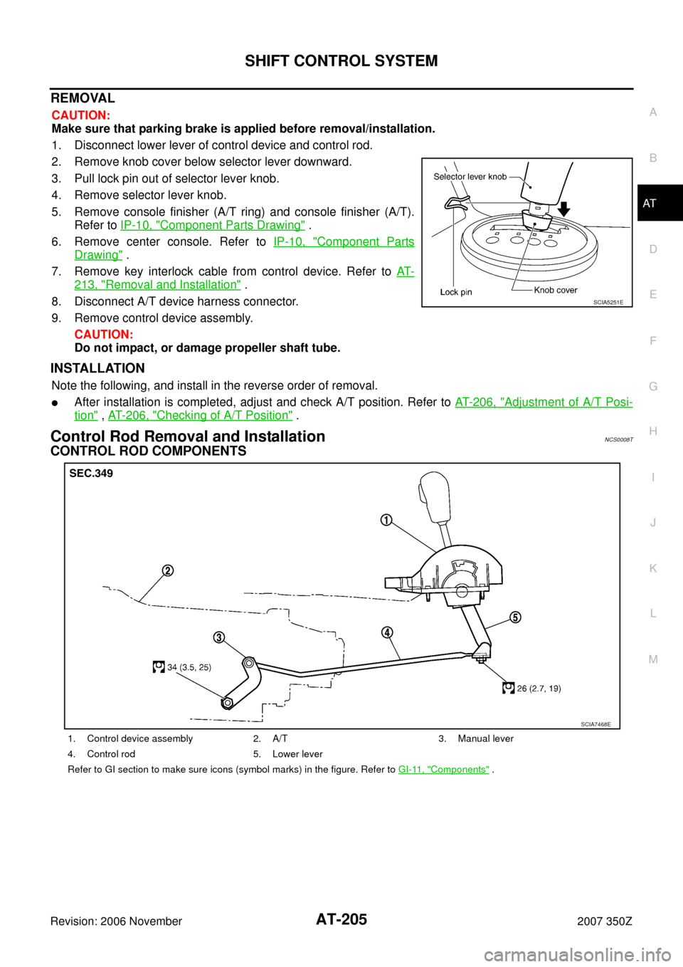
REMOVAL
CAUTION:
Make sure that parking brake is applied before removal/installation.
1. Disconnect lower lever of control device and control rod.
2. Remove knob cover below selector lever downward.
3. Pull lock pin out of selector lever knob.
4. Remove selector lever knob.
5. Remove console finisher (A/T ring) and console finisher (A/T).
Refer to IP-10, "
Component Parts Drawing" .
6. Remove center console. Refer to IP-10, "
Component Parts
Drawing" .
7. Remove key interlock cable from control device. Refer to AT-
213, "Removal and Installation" .
8. Disconnect A/T device harness connector.
9. Remove control device assembly.
CAUTION:
Do not impact, or damage propeller shaft tube.
INSTALLATION
Note the following, and install in the reverse order of removal.
�After installation is completed, adjust and check A/T position. Refer to AT- 2 0 6 , "Adjustment of A/T Posi-
tion" , AT- 2 0 6 , "Checking of A/T Position" .
Control Rod Removal and InstallationNCS0008T
CONTROL ROD COMPONENTS
SCIA5251E
1. Control device assembly 2. A/T 3. Manual lever
4. Control rod 5. Lower lever
Refer to GI section to make sure icons (symbol marks) in the figure. Refer to GI-11, "
Components" .
SCIA7468E
Page 206 of 312
AT-206
SHIFT CONTROL SYSTEM
Revision: 2006 November2007 350Z
REMOVAL
1. Disconnect lower lever of control device and control rod.
2. Remove manual lever from A/T.
3. Remove control rod from vehicle.
INSTALLATION
Note the following, and install in the reverse order of removal.
�After installation is completed, adjust and check A/T position. Refer to AT- 2 0 6 , "Adjustment of A/T Posi-
tion" and AT- 2 0 6 , "Checking of A/T Position" .
Adjustment of A/T PositionNCS0008U
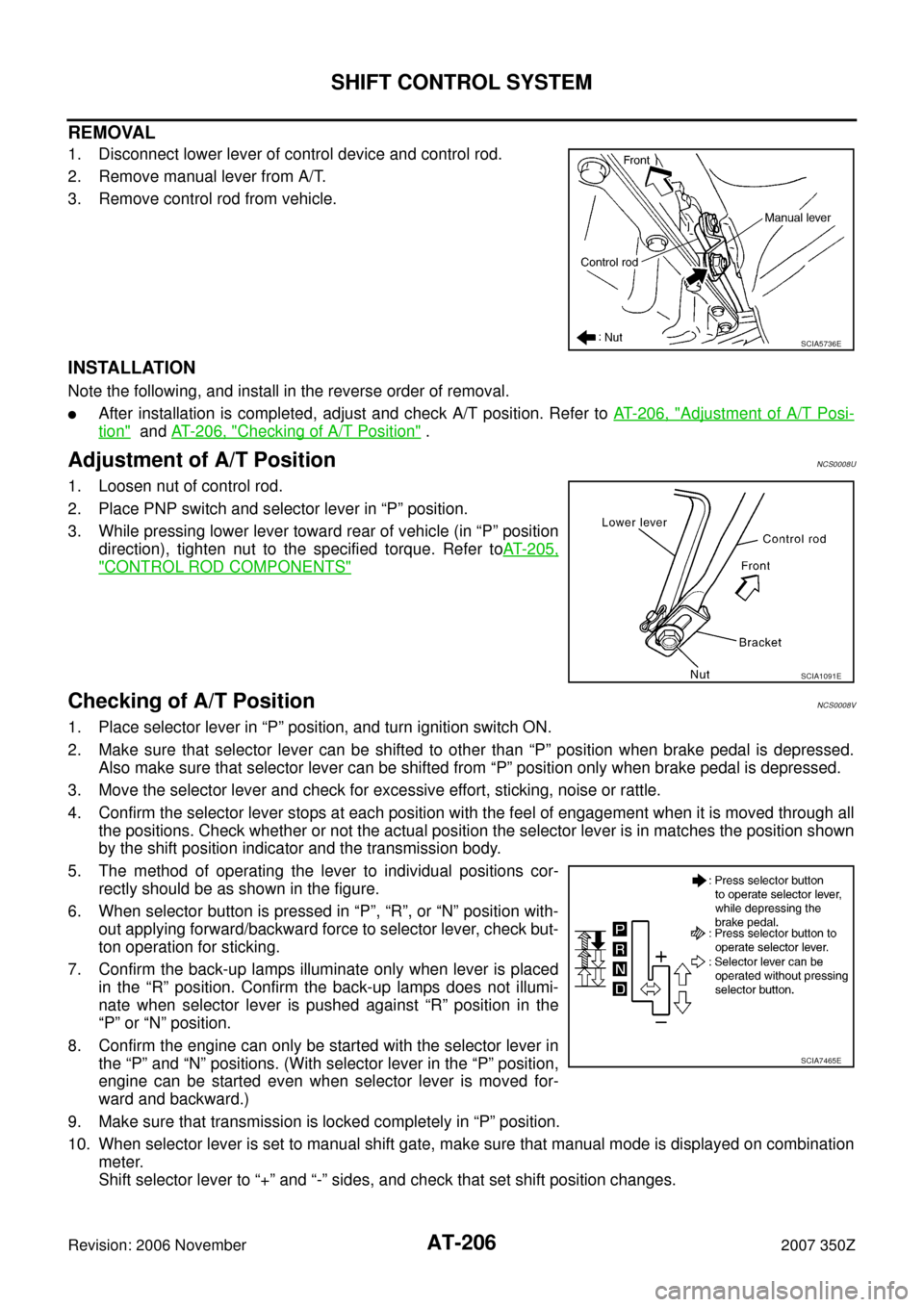
1. Loosen nut of control rod.
2. Place PNP switch and selector lever in “P” position.
3. While pressing lower lever toward rear of vehicle (in “P” position
direction), tighten nut to the specified torque. Refer toAT- 2 0 5 ,
"CONTROL ROD COMPONENTS"
Checking of A/T PositionNCS0008V
1. Place selector lever in “P” position, and turn ignition switch ON.
2. Make sure that selector lever can be shifted to other than “P” position when brake pedal is depressed.
Also make sure that selector lever can be shifted from “P” position only when brake pedal is depressed.
3. Move the selector lever and check for excessive effort, sticking, noise or rattle.
4. Confirm the selector lever stops at each position with the feel of engagement when it is moved through all
the positions. Check whether or not the actual position the selector lever is in matches the position shown
by the shift position indicator and the transmission body.
5. The method of operating the lever to individual positions cor-
rectly should be as shown in the figure.
6. When selector button is pressed in “P”, “R”, or “N” position with-
out applying forward/backward force to selector lever, check but-
ton operation for sticking.
7. Confirm the back-up lamps illuminate only when lever is placed
in the “R” position. Confirm the back-up lamps does not illumi-
nate when selector lever is pushed against “R” position in the
“P” or “N” position.
8. Confirm the engine can only be started with the selector lever in
the “P” and “N” positions. (With selector lever in the “P” position,
engine can be started even when selector lever is moved for-
ward and backward.)
9. Make sure that transmission is locked completely in “P” position.
10. When selector lever is set to manual shift gate, make sure that manual mode is displayed on combination
meter.
Shift selector lever to “+” and “-” sides, and check that set shift position changes.
SCIA5736E
SCIA1091E
SCIA7465E
Page 244 of 312
AT-244
TRANSMISSION ASSEMBLY
Revision: 2006 November2007 350Z
25. Remove engine mounting insulator (rear) with power tool. Refer to AT- 2 4 2 , "Removal and Installation" .
26. Remove bolts fixing A/T assembly to engine assembly with power tool.
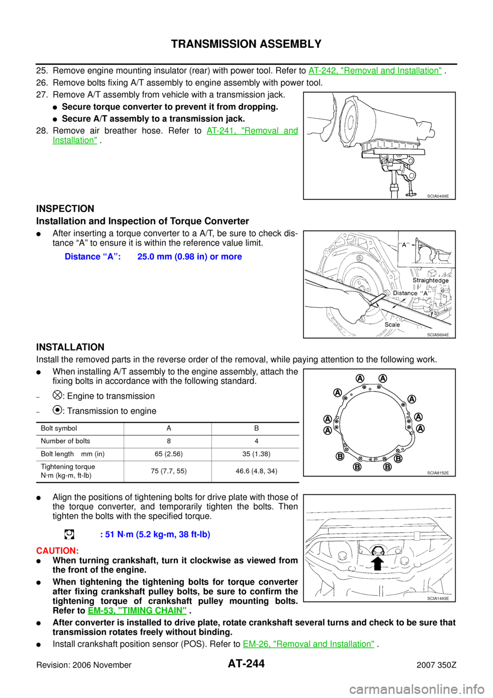
27. Remove A/T assembly from vehicle with a transmission jack.
�Secure torque converter to prevent it from dropping.
�Secure A/T assembly to a transmission jack.
28. Remove air breather hose. Refer to AT- 2 4 1 , "
Removal and
Installation" .
INSPECTION
Installation and Inspection of Torque Converter
�After inserting a torque converter to a A/T, be sure to check dis-
tance “A” to ensure it is within the reference value limit.
INSTALLATION
Install the removed parts in the reverse order of the removal, while paying attention to the following work.
�When installing A/T assembly to the engine assembly, attach the
fixing bolts in accordance with the following standard.
–: Engine to transmission
–: Transmission to engine
�Align the positions of tightening bolts for drive plate with those of
the torque converter, and temporarily tighten the bolts. Then
tighten the bolts with the specified torque.
CAUTION:
�When turning crankshaft, turn it clockwise as viewed from
the front of the engine.
�When tightening the tightening bolts for torque converter
after fixing crankshaft pulley bolts, be sure to confirm the
tightening torque of crankshaft pulley mounting bolts.
Refer to EM-53, "
TIMING CHAIN" .
�After converter is installed to drive plate, rotate crankshaft several turns and check to be sure that
transmission rotates freely without binding.
�Install crankshaft position sensor (POS). Refer to EM-26, "Removal and Installation" .
SCIA0499E
Distance “A”: 25.0 mm (0.98 in) or more
SCIA5694E
Bolt symbol A B
Number of bolts 8 4
Bolt length mm (in) 65 (2.56) 35 (1.38)
Tightening torque
N·m (kg-m, ft-lb)75 (7.7, 55) 46.6 (4.8, 34)
SCIA8152E
: 51 N·m (5.2 kg-m, 38 ft-lb)
SCIA1493E
Page 247 of 312
OVERHAUL
AT-247
D
E
F
G
H
I
J
K
L
MA
B
AT
Revision: 2006 November2007 350Z
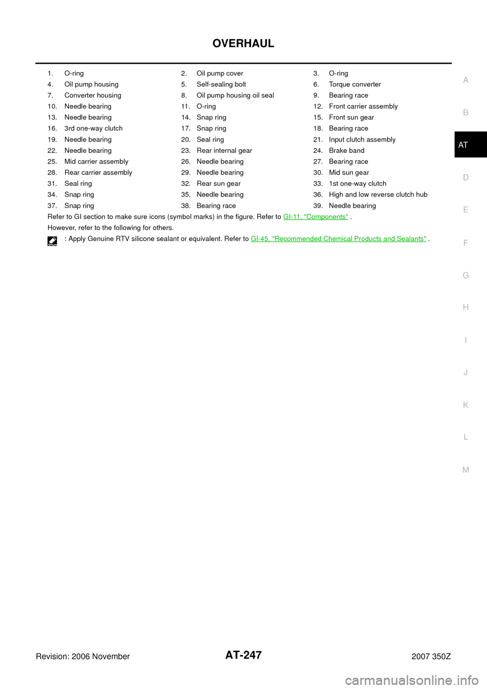
1. O-ring 2. Oil pump cover 3. O-ring
4. Oil pump housing 5. Self-sealing bolt 6. Torque converter
7. Converter housing 8. Oil pump housing oil seal 9. Bearing race
10. Needle bearing 11. O-ring 12. Front carrier assembly
13. Needle bearing 14. Snap ring 15. Front sun gear
16. 3rd one-way clutch 17. Snap ring 18. Bearing race
19. Needle bearing 20. Seal ring 21. Input clutch assembly
22. Needle bearing 23. Rear internal gear 24. Brake band
25. Mid carrier assembly 26. Needle bearing 27. Bearing race
28. Rear carrier assembly 29. Needle bearing 30. Mid sun gear
31. Seal ring 32. Rear sun gear 33. 1st one-way clutch
34. Snap ring 35. Needle bearing 36. High and low reverse clutch hub
37. Snap ring 38. Bearing race 39. Needle bearing
Refer to GI section to make sure icons (symbol marks) in the figure. Refer to GI-11, "
Components" .
However, refer to the following for others.
: Apply Genuine RTV silicone sealant or equivalent. Refer to GI-45, "
Recommended Chemical Products and Sealants" .
Page 248 of 312
AT-248
OVERHAUL
Revision: 2006 November2007 350Z
1. Needle bearing 2. Bearing race 3. High and low reverse clutch assembly
4. Needle bearing 5. Direct clutch assembly 6. Reverse brake dish plate
7. Reverse brake dish plate 8. Reverse brake driven plate 9. N-spring
SCIA8377E
Page 249 of 312
OVERHAUL
AT-249
D
E
F
G
H
I
J
K
L
MA
B
AT
Revision: 2006 November2007 350Z
10. Reverse brake drive plate 11. Reverse brake retaining plate 12. Snap ring
13. D-ring 14. D-ring 15. Reverse brake piston
16. Return spring 17. Spring retainer 18. Snap ring
Refer to GI section to make sure icons (symbol marks) in the figure. Refer to GI-11, "
Components" .
Page 259 of 312
DISASSEMBLY
AT-259
D
E
F
G
H
I
J
K
L
MA
B
AT
Revision: 2006 November2007 350Z
19. Remove needle bearing (front side) from mid carrier assembly.
20. Remove needle bearing (rear side) from mid carrier assembly.
21. Remove bearing race from rear carrier assembly.
22. Remove needle bearing from rear carrier assembly.
23. Remove mid sun gear assembly, rear sun gear assembly and
high and low reverse clutch hub as a unit.
CAUTION:
Be careful to remove then with bearing race and needle
bearing.
SCIA2805E
SCIA2804E
SCIA5175E
SCIA2803E
SCIA5018E