Page 206 of 312

AT-206
SHIFT CONTROL SYSTEM
Revision: 2006 November2007 350Z
REMOVAL
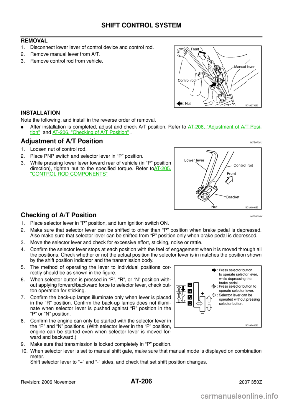
1. Disconnect lower lever of control device and control rod.
2. Remove manual lever from A/T.
3. Remove control rod from vehicle.
INSTALLATION
Note the following, and install in the reverse order of removal.
�After installation is completed, adjust and check A/T position. Refer to AT- 2 0 6 , "Adjustment of A/T Posi-
tion" and AT- 2 0 6 , "Checking of A/T Position" .
Adjustment of A/T PositionNCS0008U
1. Loosen nut of control rod.
2. Place PNP switch and selector lever in “P” position.
3. While pressing lower lever toward rear of vehicle (in “P” position
direction), tighten nut to the specified torque. Refer toAT- 2 0 5 ,
"CONTROL ROD COMPONENTS"
Checking of A/T PositionNCS0008V
1. Place selector lever in “P” position, and turn ignition switch ON.
2. Make sure that selector lever can be shifted to other than “P” position when brake pedal is depressed.
Also make sure that selector lever can be shifted from “P” position only when brake pedal is depressed.
3. Move the selector lever and check for excessive effort, sticking, noise or rattle.
4. Confirm the selector lever stops at each position with the feel of engagement when it is moved through all
the positions. Check whether or not the actual position the selector lever is in matches the position shown
by the shift position indicator and the transmission body.
5. The method of operating the lever to individual positions cor-
rectly should be as shown in the figure.
6. When selector button is pressed in “P”, “R”, or “N” position with-
out applying forward/backward force to selector lever, check but-
ton operation for sticking.
7. Confirm the back-up lamps illuminate only when lever is placed
in the “R” position. Confirm the back-up lamps does not illumi-
nate when selector lever is pushed against “R” position in the
“P” or “N” position.
8. Confirm the engine can only be started with the selector lever in
the “P” and “N” positions. (With selector lever in the “P” position,
engine can be started even when selector lever is moved for-
ward and backward.)
9. Make sure that transmission is locked completely in “P” position.
10. When selector lever is set to manual shift gate, make sure that manual mode is displayed on combination
meter.
Shift selector lever to “+” and “-” sides, and check that set shift position changes.
SCIA5736E
SCIA1091E
SCIA7465E
Page 236 of 312

AT-236
ON-VEHICLE SERVICE
Revision: 2006 November2007 350Z
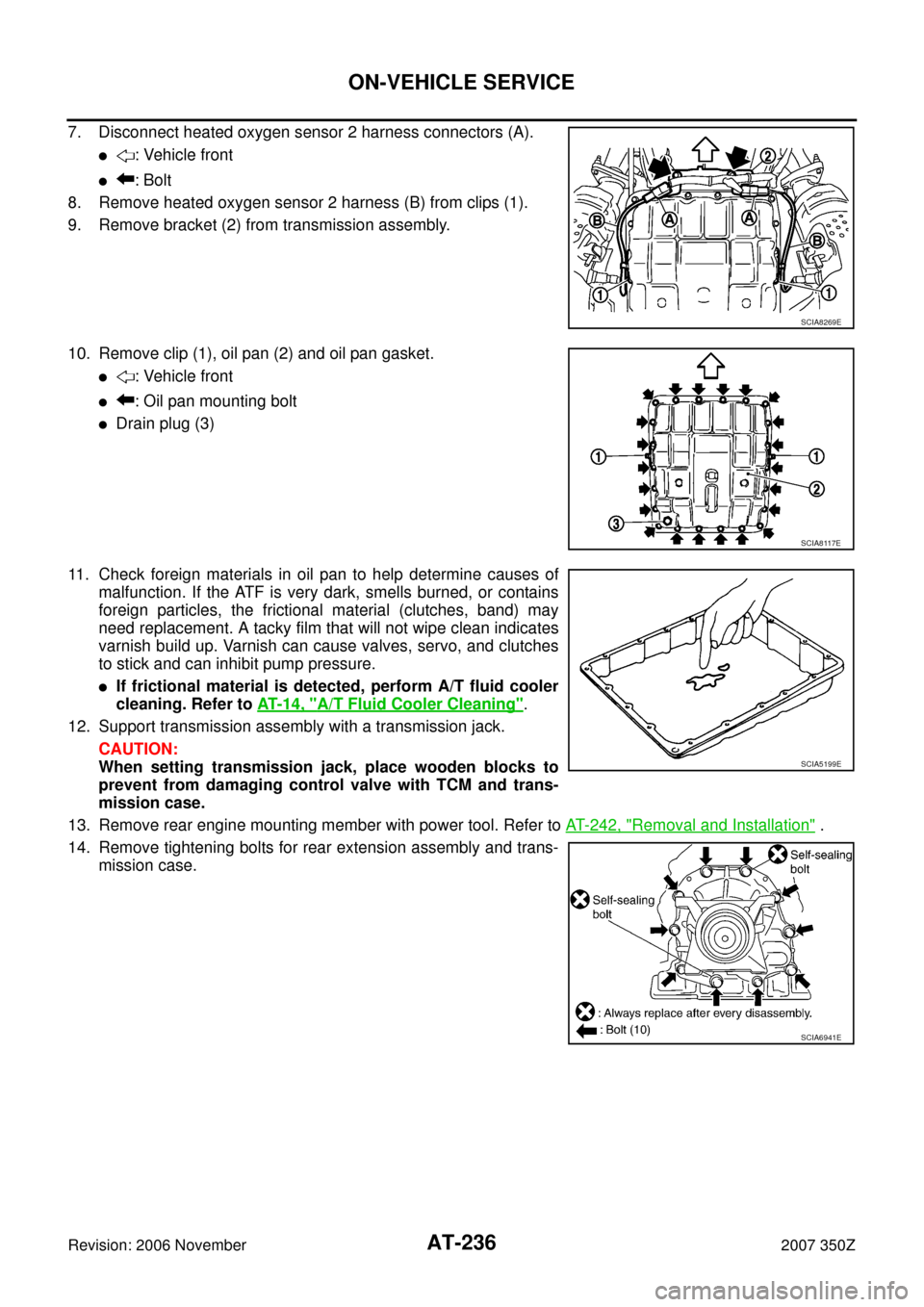
7. Disconnect heated oxygen sensor 2 harness connectors (A).
�: Vehicle front
�: Bolt
8. Remove heated oxygen sensor 2 harness (B) from clips (1).
9. Remove bracket (2) from transmission assembly.
10. Remove clip (1), oil pan (2) and oil pan gasket.
�: Vehicle front
�: Oil pan mounting bolt
�Drain plug (3)
11. Check foreign materials in oil pan to help determine causes of
malfunction. If the ATF is very dark, smells burned, or contains
foreign particles, the frictional material (clutches, band) may
need replacement. A tacky film that will not wipe clean indicates
varnish build up. Varnish can cause valves, servo, and clutches
to stick and can inhibit pump pressure.
�If frictional material is detected, perform A/T fluid cooler
cleaning. Refer to AT- 1 4 , "
A/T Fluid Cooler Cleaning".
12. Support transmission assembly with a transmission jack.
CAUTION:
When setting transmission jack, place wooden blocks to
prevent from damaging control valve with TCM and trans-
mission case.
13. Remove rear engine mounting member with power tool. Refer to AT- 2 4 2 , "
Removal and Installation" .
14. Remove tightening bolts for rear extension assembly and trans-
mission case.
SCIA8269E
SCIA8117E
SCIA5199E
SCIA6941E
Page 244 of 312

AT-244
TRANSMISSION ASSEMBLY
Revision: 2006 November2007 350Z
25. Remove engine mounting insulator (rear) with power tool. Refer to AT- 2 4 2 , "Removal and Installation" .
26. Remove bolts fixing A/T assembly to engine assembly with power tool.
27. Remove A/T assembly from vehicle with a transmission jack.
�Secure torque converter to prevent it from dropping.
�Secure A/T assembly to a transmission jack.
28. Remove air breather hose. Refer to AT- 2 4 1 , "
Removal and
Installation" .
INSPECTION
Installation and Inspection of Torque Converter
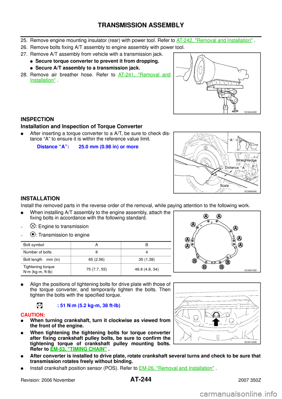
�After inserting a torque converter to a A/T, be sure to check dis-
tance “A” to ensure it is within the reference value limit.
INSTALLATION
Install the removed parts in the reverse order of the removal, while paying attention to the following work.
�When installing A/T assembly to the engine assembly, attach the
fixing bolts in accordance with the following standard.
–: Engine to transmission
–: Transmission to engine
�Align the positions of tightening bolts for drive plate with those of
the torque converter, and temporarily tighten the bolts. Then
tighten the bolts with the specified torque.
CAUTION:
�When turning crankshaft, turn it clockwise as viewed from
the front of the engine.
�When tightening the tightening bolts for torque converter
after fixing crankshaft pulley bolts, be sure to confirm the
tightening torque of crankshaft pulley mounting bolts.
Refer to EM-53, "
TIMING CHAIN" .
�After converter is installed to drive plate, rotate crankshaft several turns and check to be sure that
transmission rotates freely without binding.
�Install crankshaft position sensor (POS). Refer to EM-26, "Removal and Installation" .
SCIA0499E
Distance “A”: 25.0 mm (0.98 in) or more
SCIA5694E
Bolt symbol A B
Number of bolts 8 4
Bolt length mm (in) 65 (2.56) 35 (1.38)
Tightening torque
N·m (kg-m, ft-lb)75 (7.7, 55) 46.6 (4.8, 34)
SCIA8152E
: 51 N·m (5.2 kg-m, 38 ft-lb)
SCIA1493E
Page 311 of 312

SERVICE DATA AND SPECIFICATIONS (SDS)
AT-311
D
E
F
G
H
I
J
K
L
MA
B
AT
Revision: 2006 November2007 350Z
SERVICE DATA AND SPECIFICATIONS (SDS)PFP:00030
General SpecificationsNCS0009L
�*1: Refer to MA-11, "Fluids and Lubricants" .
�*2: The fluid capacity is the reference value. Check the fluid level with A/T fluid level gauge.
Vehicle Speed at Which Gear Shifting OccursNCS0009M
�At half throttle, the accelerator opening is 4/8 of the full opening.
Vehicle Speed at Which Lock-up Occurs/ReleasesNCS0009N
�At closed throttle, the accelerator opening is less than 1/8 condition. (Closed throttle position signal: OFF)
�At half throttle, the accelerator opening is 4/8 of the full opening.
Stall SpeedNCS0009O
Line PressureNCS0009P
Applied modelVQ35HR engine
Automatic transmission model RE5R05A
Transmission model code number 98X5B
Stall torque ratio1.74 : 1
Transmission gear ratio1st 3.842
2nd 2.353
3rd 1.529
4th 1.000
5th 0.839
Reverse 2.765
Recommended fluid
Genuine NISSAN Matic J ATF
*1
Fluid capacity
10.3 liter (10-7/8 US qt, 9-1/8 Imp qt)*2
CAUTION:
�Use only Genuine NISSAN Matic J ATF. Do not mix with other fluid.
�Using A/T fluid other than Genuine NISSAN Matic J ATF will cause deterioration driveability and automatic transmission
durability, and may damage the automatic transmission, which is not covered by the NISSAN new vehicle limited warranty.
Throttle positionVehicle speed km/h (MPH)
D1 →D2D2 →D3D3 →D4D4 →D5D5 →D4D4 →D3D3 →D2D2 →D1
Full throttle 50 – 54
(31 – 34)97 – 105
(60 – 65)154 – 164
(96 – 102)224 – 234
(139 – 145)220 – 230
(137 – 143)145 – 155
(90 – 96)86 – 94
(53 – 58)39 – 43
(24 – 27)
Half throttle 29 – 33
(18 – 21)63 – 69
(39 – 43)100 – 108
(62 – 67)136 – 144
(85 – 89)88 – 96
(55 – 60)64 – 72
(40 – 45)28 – 34
(17 – 21)9 – 13
(6 – 8)
Throttle positionVehicle speed km/h (MPH)
Lock-up ON Lock-up OFF
Closed throttle 62 – 70 (39 – 44) 59 – 67 (37 – 42)
Half throttle 136 – 144 (85 – 89) 88 – 96 (55 – 60)
Stall speed2,700 – 3,000 rpm
Engine speedLine pressure kPa (kg/cm
2 , psi)
“R” position “D” and “M” positions
At idle speed 425 – 465 (4.3 – 4.7, 62 – 67) 379 – 428 (3.9 – 4.4, 55 – 62)
At stall speed 1,605 – 1,950 (16.4 – 19.9, 233 – 283) 1,310 – 1,500 (13.4 – 15.3, 190 – 218)