Page 49 of 142

TROUBLE DIAGNOSIS
ATC-49
C
D
E
F
G
H
I
K
L
MA
B
AT C
Revision: 2006 November2007 350Z
9. CHECK MALFUNCTIONING SENSOR AND DOOR MOTOR
Refer to the following chart.
*1: Perform self-diagnosis STEP-2 under sunshine.
When performing indoors, aim a light (more than 60 W) at sunload
sensor, otherwise LED of A/C switch will not indicate despite that
sunload sensor is functioning properly.
NOTE:
When switched to STEP-2, LED of REC position blinks for approxi-
mately 25 seconds.
*2: AT C - 9 2 , "
DIAGNOSIS PROCEDURE FOR AMBIENT SENSOR" .
*3: AT C - 9 5 , "
DIAGNOSIS PROCEDURE FOR IN-VEHICLE SENSOR" .
*4: AT C - 9 7 , "
DIAGNOSIS PROCEDURE FOR SUNLOAD SENSOR" .
*5: ATC-100, "
DIAGNOSIS PROCEDURE FOR INTAKE SENSOR" .
*6: AT C - 6 5 , "
DIAGNOSIS PROCEDURE FOR AIR MIX DOOR MOTOR PBR" .
>> INSPECTION END
10. CHECK MALFUNCTIONING DOOR MOTOR POSITION SWITCH
Mode and/or intake door motor PBR(s) is/are malfunctioning.
NOTE:
When switched to STEP-3, LED of REC position blinks for approxi-
mately 50 seconds.
*1: AT C - 6 2 , "
DIAGNOSIS PROCEDURE FOR MODE DOOR
MOTOR" .
*2: AT C - 6 8 , "
DIAGNOSIS PROCEDURE FOR INTAKE DOOR
MOTOR" .
>> INSPECTION END
S J I A 111 5 E
Mode control dial position Unusual Malfunctioning sensor and door motor (Including circuits) Reference page
VENT
A/C LED: OFFAmbient sensor *2
B/L In-vehicle sensor *3
FOOT or FOOT2
Sunload sensor
*1*4
D/F or D/F2 Intake sensor *5
DEF Air mix door motor (LCU) PBR *6
Unusual Mode or intake door position Reference page
REC LED: ON Mode door motor *1
FRE LED: ON Intake door motor *2
S J I A 111 6 E
Page 50 of 142
 between temperature setti")
ATC-50
TROUBLE DIAGNOSIS
Revision: 2006 November2007 350Z
AUXILIARY MECHANISM: TEMPERATURE SETTING TRIMMER
The trimmer compensates for differences in range of ±3°C (±6°F) between temperature setting (temperature
control dial position) and temperature felt by customer.
Operating procedures for this trimmer are as follows:
1. Set fan control dial to OFF.
2. Turn ignition switch ON.
3. Set in self-diagnosis mode as follows. Within 10 seconds after starting engine (ignition switch is turned
ON.), press intake switch for at least 5 seconds.
4. When intake switch is pressed, temperature shifts in following order: 0°C (0°F)→ 1°C (2°F)→ 2°C (4°F)→
3°C (6°F)→ −3°C (−6°F)→ −2°C (−4°F)→ −1°C (−2°F)→ return to 0°C (0°F).
When battery cable is disconnected or battery voltage is below 9 V, trimmer operation is canceled. Tempera-
ture set becomes that of initial condition, i.e. 0°C (0°F).
Setting temperatureLED status of each switch
FRE REC A/C
−3°C (−6°F) ON ON ON
−2°C (−4°F) ON ON OFF
−1°C (−2°F) ON OFF ON
0°C (0°F) (Initial setting) OFF OFF OFF
1°C (2°F) OFF OFF ON
2°C (4°F) OFF ON OFF
3°C (6°F) OFF ON ON
Page 51 of 142

TROUBLE DIAGNOSIS
ATC-51
C
D
E
F
G
H
I
K
L
MA
B
AT C
Revision: 2006 November2007 350Z
AUXILIARY MECHANISM: FOOT POSITION SETTING TRIMMER
Wind distribution ratio in FOOT mode can be set.
Operating procedures for this trimmer are as follows:
1. Set fan control dial to AUTO.
2. Turn ignition switch ON.
3. Set in self-diagnosis mode as follows. Within 10 seconds after starting engine (ignition switch is turned
ON.), press intake switch for at least 5 seconds.
4. Press intake switch as desired.
When battery cable is disconnected or battery voltage is below 9 V, trimmer operation is canceled. Wind distri-
bution ratio set becomes that of initial condition.
AUXILIARY MECHANISM: INLET PORT MEMORY FUNCTION
When ignition switch is turned from OFF to ON, inlet port memory function at manual mode can be set.
Operating procedures for this trimmer are as follows:
1. Set fan control dial to 1st - 12th speed.
2. Turn ignition switch ON.
3. Set in self-diagnosis mode as follows. Within 10 seconds after starting engine (ignition switch is turned
ON.), press intake switch for at least 5 seconds.
4. Press intake switch as desired.
RJIA1365E
Ty p eLED status of each switch
FRE REC A/C
Type-A (Initial setting) OFF OFF ON
Ty p e - B O F F O N O F F
Type-C OFF ON ON
Type-D ON OFF OFF
LED status of
FRE positionLED status of
REC positionSetting status
Setting changeover
method
FRE REC
OFF OFF AUTO control AUTO control
Intake SW: ON OFF ON AUTO control (Initial setting)Manual REC status is memorized.
(Initial setting)
ON ON Manual FRE status is memorized. AUTO control
ON OFF Manual FRE status is memorized. Manual REC status is memorized.
Page 52 of 142
ATC-52
TROUBLE DIAGNOSIS
Revision: 2006 November2007 350Z
When battery cable is disconnected or battery voltage is below 9 V, memory function is canceled. Memory
function set becomes that of initial condition.
Page 53 of 142

TROUBLE DIAGNOSIS
ATC-53
C
D
E
F
G
H
I
K
L
MA
B
AT C
Revision: 2006 November2007 350Z
Operational CheckNJS0000X
The purpose of the operational check is to check if the individual system operates properly.
CHECKING BLOWER
1. Turn fan control dial to 1st speed. Blower should operate on low speed.
2. Turn fan control dial to 2nd speed, and continue checking blower speed until all speeds are checked.
3. Leave blower on max. speed.
If NG, go to trouble diagnosis procedure for AT C - 6 9 , "
Blower Motor Circuit" .
If OK, continue the check.
CHECKING DISCHARGE AIR
1. Turn mode control dial to each position.
2. Confirm that discharge air comes out according to the air distri-
bution table. Refer to AT C - 3 0 , "
Discharge Air Flow" .
Intake door position is checked in the next step.
If NG, go to trouble diagnosis procedure for AT C - 6 0 , "
Mode Door
Motor Circuit" .
If OK, continue the check.
NOTE:
Confirm that the compressor clutch is engaged (sound or visual
inspection) and intake door position is at FRESH when the D/F, D/F2
or DEF position are selected.
CHECKING INTAKE DOOR
1. Press intake switch. Recirculation LED should illuminate.
2. Press intake switch again. Fresh LED should illuminate.
3. Listen for intake door position change. (Slight change of blower sound can be heard.)
If NG, go to trouble diagnosis procedure for AT C - 6 6 , "
Intake Door Motor Circuit" .
If OK, continue the check.
CHECKING TEMPERATURE DECREASE
1. Turn temperature control dial until 18°C (60°F).
2. Check for cold air at discharge air outlets.
If NG, go to trouble diagnosis procedure for AT C - 8 1 , "
Insufficient Cooling" .
If OK, continue the check.
CHECKING TEMPERATURE INCREASE
1. Turn temperature control dial until 32°C (90°F).
2. Check for hot air at discharge air outlets.
If NG, go to trouble diagnosis procedure for AT C - 8 9 , "
Insufficient Heating" .
If OK, continue the check.
CHECKING A/C SWITCH
Turn fan control dial to AUTO position. (Compressor is turned ON automatically.)
�Confirm that the compressor clutch engages (sound or visual inspection). (Discharge air and blower
speed will depend on ambient, in-vehicle, and set temperatures.)
If NG, go to trouble diagnosis procedure for AT C - 5 4 , "
Power Supply and Ground Circuit for Auto Amp." , then
if necessary, trouble diagnosis procedure for AT C - 7 4 , "
Magnet Clutch Circuit" .
If all operational checks are OK (symptom cannot be duplicated), go to Incident Simulation Tests in GI-27,
"How to Perform Efficient Diagnosis for an Electrical Incident" and perform tests as outlined to simulate driv-
ing conditions environment. If symptom appears, refer to AT C - 3 4 , "
SYMPTOM TABLE" and perform applica-
ble trouble diagnosis procedures.Conditions : Engine running at normal operating temperature
RJIA2110E
Page 54 of 142
ATC-54
TROUBLE DIAGNOSIS
Revision: 2006 November2007 350Z
Power Supply and Ground Circuit for Auto Amp.NJS0000Y
SYMPTOM: A/C system does not come on.
INSPECTION FLOW
COMPONENT DESCRIPTION
Unified Meter and A/C amp. (Automatic Amplifier)
The unified meter and A/C amp. has a built-in microcomputer which
processes information sent from various sensors needed for air con-
ditioner operation. The air mix door motor, mode door motor, intake
door motor, blower motor and compressor are then controlled.
When the various switches and temperature control dial are oper-
ated, data is input to the unified meter and A/C amp. from the A/C
controller using multiplex communication.
Self-diagnosis functions are also built into unified meter and A/C
amp. to provide quick check of malfunctions in the auto air condi-
tioner system.
*1AT C - 5 5 , "DIAGNOSIS PROCE-
DURE FOR A/C SYSTEM"
*2AT C - 5 3 , "Operational Check"
SJIA1123E
RJIA1356E
Page 55 of 142

The PTC is built into the A/C controller. It can be set at an interval of
1°C")
TROUBLE DIAGNOSIS
ATC-55
C
D
E
F
G
H
I
K
L
MA
B
AT C
Revision: 2006 November2007 350Z
Potentio Temperature Control (PTC)
The PTC is built into the A/C controller. It can be set at an interval of
1°C (2.0°F) in the 18°C (60°F) to 32°C (90°F) temperature range by
turning the temperature control dial.
DIAGNOSIS PROCEDURE FOR A/C SYSTEM
SYMPTOM: A/C system does not come on.
1. CHECK POWER SUPPLY CIRCUIT FOR UNIFIED METER AND A/C AMP.
1. Disconnect unified meter connector and A/C amp. connector.
2. Check voltage between unified meter and A/C amp. harness
connector M49 terminal 21 and 22, unified meter and A/C amp.
harness connector M50 terminal 46 and ground.
OK or NG
OK >> GO TO 2.
NG >> Check 10A and 15A fuses [Nos. 10, 11, 12 and 19, located in the fuse block (J/B)]. Refer to PG-
85, "FUSE BLOCK - JUNCTION BOX (J/B)" .
�If fuses are OK, check harness for open circuit. Repair or replace if necessary.
�If fuses are NG, check harness for short circuit and replace fuse.
SJIA1124E
RJIA1374E
Terminals Ignition switch position
(+)
(−)OFF ACC ON Unified
meter and
A/C amp.
connectorTerminal No.
M49 21
GroundBattery
voltageBattery
voltageBattery
voltage
M49 22 Approx. 0 V Approx. 0 VBattery
voltage
M50 46 Approx. 0 VBattery
voltageBattery
voltage
RJIA2121E
Page 56 of 142
ATC-56
TROUBLE DIAGNOSIS
Revision: 2006 November2007 350Z
2. CHECK GROUND CIRCUIT FOR UNIFIED METER AND A/C AMP.
1. Turn ignition switch OFF.
2. Check continuity between unified meter and A/C amp. harness
connector M49 terminal 29, 30 and ground.
OK or NG
OK >> Replace unified meter and A/C amp.
NG >> Repair harness or connector.
LAN System CircuitNJS0000Z
SYMPTOM: Mode door motor, intake door motor and/or air mix door motor does not operate normally.
DIAGNOSIS PROCEDURE FOR LAN CIRCUIT
1. CHECK POWER SUPPLY FOR UNIFIED METER AND A/C AMP.
1. Turn ignition switch ON.
2. Check voltage between unified meter and A/C amp. harness
connector M50 terminal 54 and ground.
OK or NG
OK >> GO TO 2.
NG >> Replace unified meter and A/C amp.29, 30 – Ground : Continuity should exist.
RJIA1985E
RJIA2122E
54 – Ground : Battery voltage
RJIA1986E
 1
1 2
2 3
3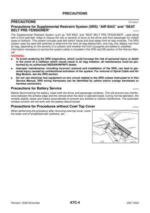 4
4 5
5 6
6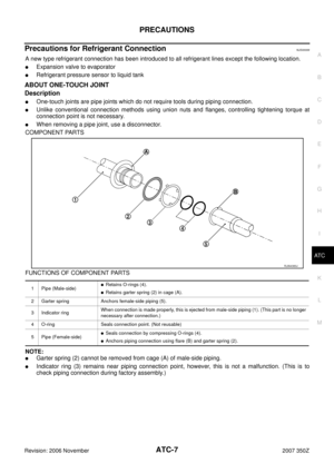 7
7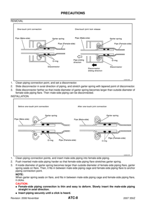 8
8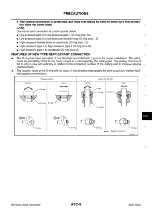 9
9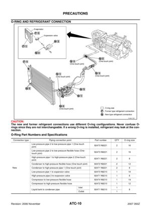 10
10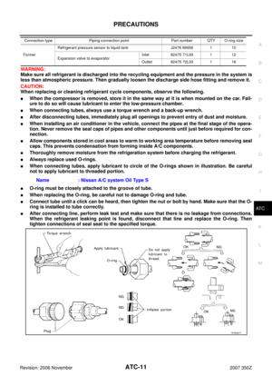 11
11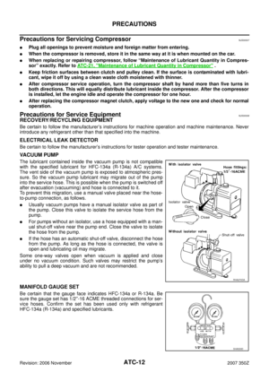 12
12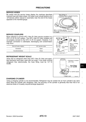 13
13 14
14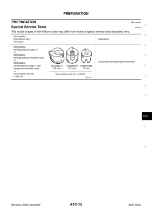 15
15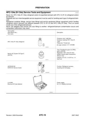 16
16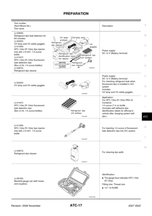 17
17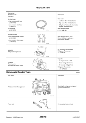 18
18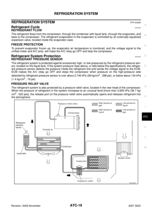 19
19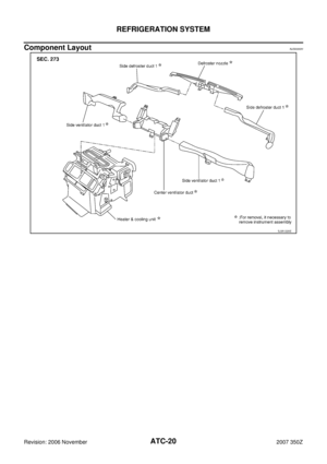 20
20 21
21 22
22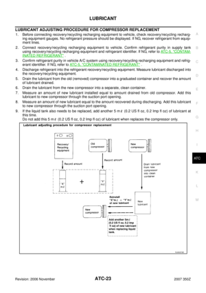 23
23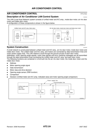 24
24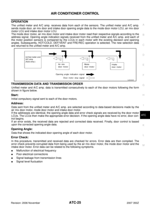 25
25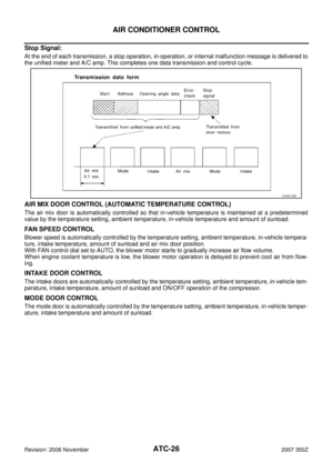 26
26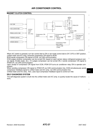 27
27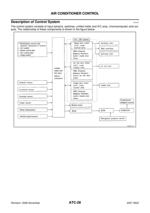 28
28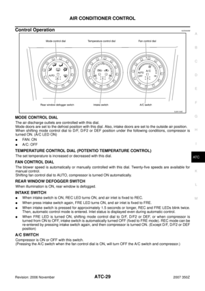 29
29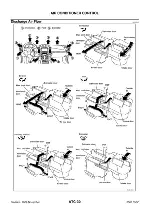 30
30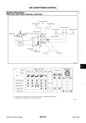 31
31 32
32 33
33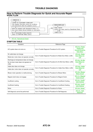 34
34 35
35 36
36 37
37 38
38 39
39 40
40 41
41 42
42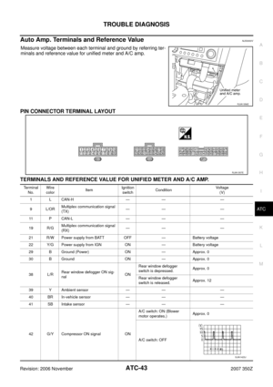 43
43 44
44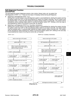 45
45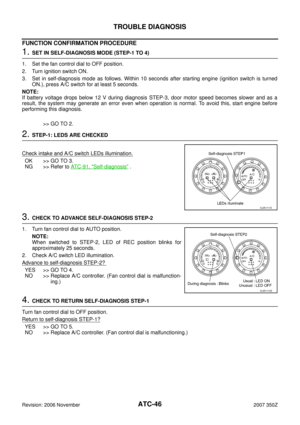 46
46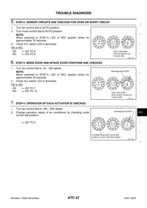 47
47 48
48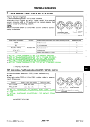 49
49 50
50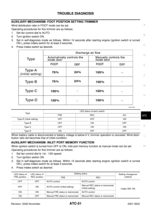 51
51 52
52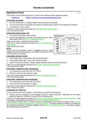 53
53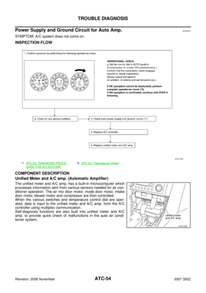 54
54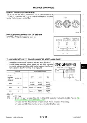 55
55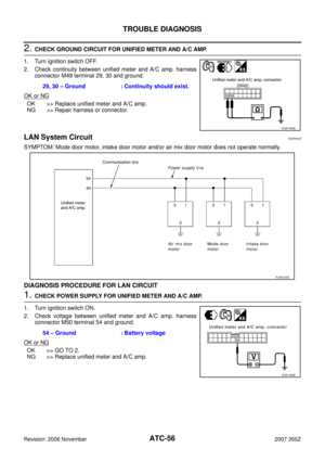 56
56 57
57 58
58 59
59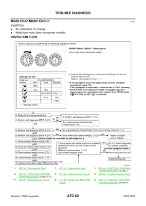 60
60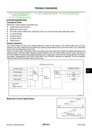 61
61 62
62 63
63 64
64 65
65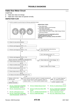 66
66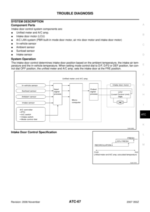 67
67 68
68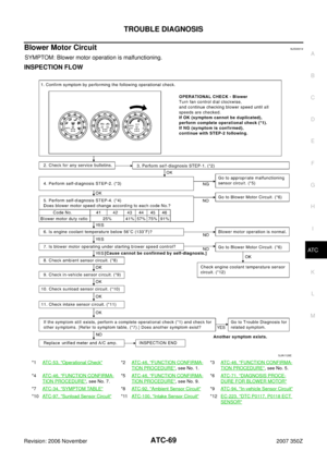 69
69 70
70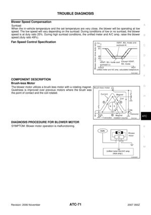 71
71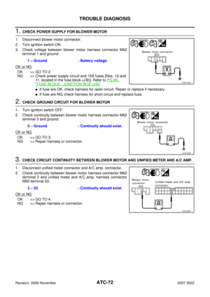 72
72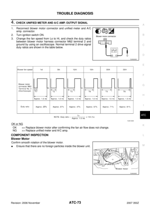 73
73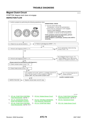 74
74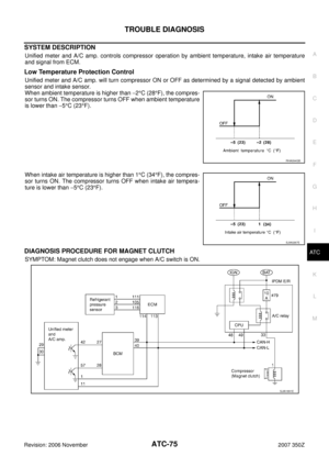 75
75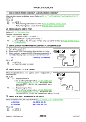 76
76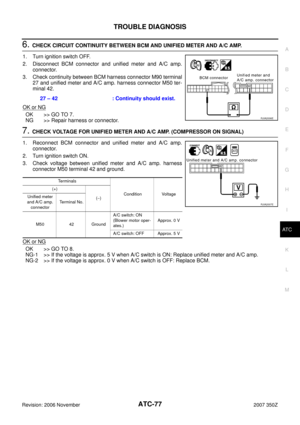 77
77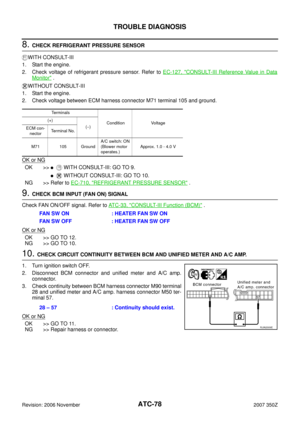 78
78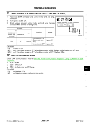 79
79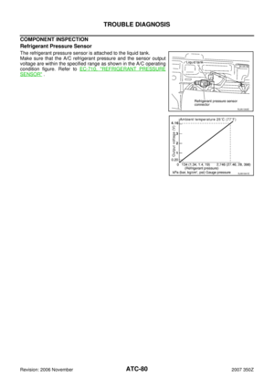 80
80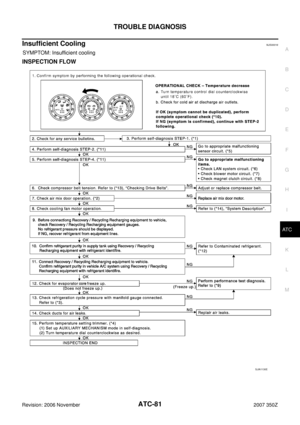 81
81 82
82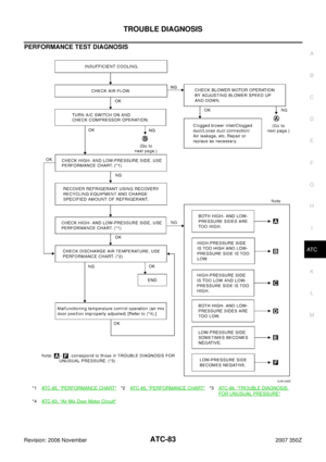 83
83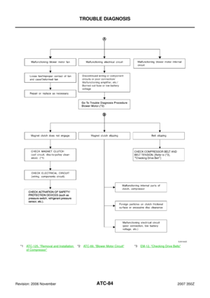 84
84 85
85 86
86 87
87 88
88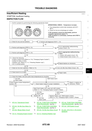 89
89 90
90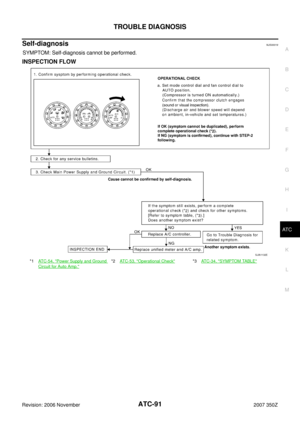 91
91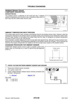 92
92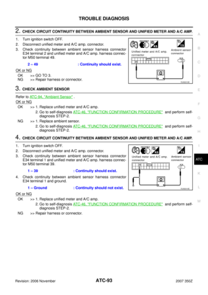 93
93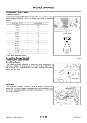 94
94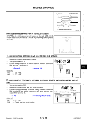 95
95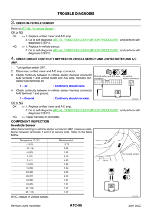 96
96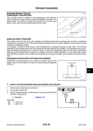 97
97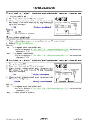 98
98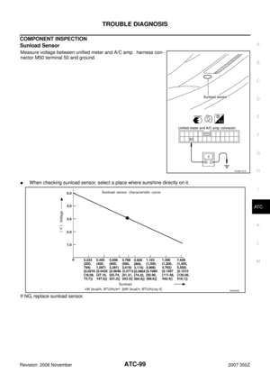 99
99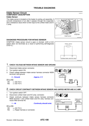 100
100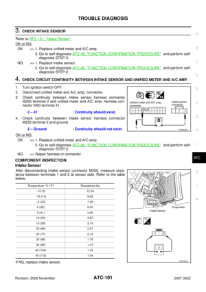 101
101 102
102 103
103 104
104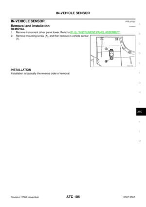 105
105 106
106 107
107 108
108 109
109 110
110 111
111 112
112 113
113 114
114 115
115 116
116 117
117 118
118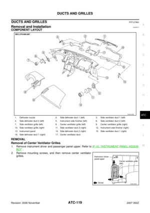 119
119 120
120 121
121 122
122 123
123 124
124 125
125 126
126 127
127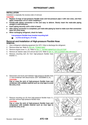 128
128 129
129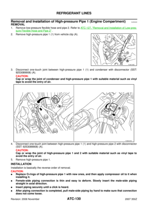 130
130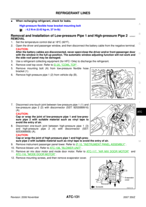 131
131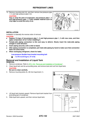 132
132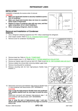 133
133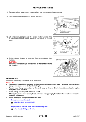 134
134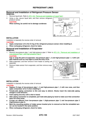 135
135 136
136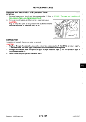 137
137 138
138 139
139 140
140 141
141

