Page 101 of 142

TROUBLE DIAGNOSIS
ATC-101
C
D
E
F
G
H
I
K
L
MA
B
AT C
Revision: 2006 November2007 350Z
3. CHECK INTAKE SENSOR
Refer to ATC-101, "
Intake Sensor" .
OK or NG
OK >> 1. Replace unified meter and A/C amp.
2. Go to self-diagnosis AT C - 4 6 , "
FUNCTION CONFIRMATION PROCEDURE" and perform self-
diagnosis STEP-2.
NG >> 1. Replace intake sensor.
2. Go to self-diagnosis AT C - 4 6 , "
FUNCTION CONFIRMATION PROCEDURE" and perform self-
diagnosis STEP-2.
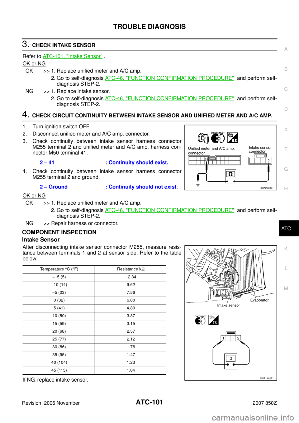
4. CHECK CIRCUIT CONTINUITY BETWEEN INTAKE SENSOR AND UNIFIED METER AND A/C AMP.
1. Turn ignition switch OFF.
2. Disconnect unified meter and A/C amp. connector.
3. Check continuity between intake sensor harness connector
M255 terminal 2 and unified meter and A/C amp. harness con-
nector M50 terminal 41.
4. Check continuity between intake sensor harness connector
M255 terminal 2 and ground.
OK or NG
OK >> 1. Replace unified meter and A/C amp.
2. Go to self-diagnosis AT C - 4 6 , "
FUNCTION CONFIRMATION PROCEDURE" and perform self-
diagnosis STEP-2.
NG >> Repair harness or connector.
COMPONENT INSPECTION
Intake Sensor
After disconnecting intake sensor connector M255, measure resis-
tance between terminals 1 and 2 at sensor side. Refer to the table
below.
If NG, replace intake sensor.2 – 41 : Continuity should exist.
2 – Ground : Continuity should not exist.
RJIA2033E
Temperature °C (°F) Resistance kΩ
−15 (5) 12.34
−10 (14) 9.62
−5 (23) 7.56
0 (32) 6.00
5 (41) 4.80
10 (50) 3.87
15 (59) 3.15
20 (68) 2.57
25 (77) 2.12
30 (86) 1.76
35 (95) 1.47
40 (104) 1.23
45 (113) 1.04
RJIA1462E
Page 104 of 142
ATC-104
AMBIENT SENSOR
Revision: 2006 November2007 350Z
AMBIENT SENSORPFP:27722
Removal and InstallationNJS0001G
REMOVAL
1. Disconnect ambient sensor connector.
2. Remove ambient sensor.
INSTALLATION
Installation is basically the reverse order of removal.
RJIA1398E
Page 105 of 142
IN-VEHICLE SENSOR
ATC-105
C
D
E
F
G
H
I
K
L
MA
B
AT C
Revision: 2006 November2007 350Z
IN-VEHICLE SENSORPFP:27720
Removal and InstallationNJS0001H
REMOVAL
1. Remove instrument driver panel lower. Refer to IP-10, "INSTRUMENT PANEL ASSEMBLY" .
2. Remove mounting screw (A), and then remove in-vehicle sensor
(1).
INSTALLATION
Installation is basically the reverse order of removal.
PJIA0170E
Page 106 of 142
ATC-106
SUNLOAD SENSOR
Revision: 2006 November2007 350Z
SUNLOAD SENSORPFP:27721
Removal and InstallationNJS0001I
REMOVAL
1. Pull out sunload sensor from instrument panel.
2. Disconnect sunload sensor connector, and then remove sunload
sensor.
INSTALLATION
Installation is basically the reverse order of removal.
RJIA1404E
Page 107 of 142

INTAKE SENSOR
ATC-107
C
D
E
F
G
H
I
K
L
MA
B
AT C
Revision: 2006 November2007 350Z
INTAKE SENSORPFP:27723
Removal and InstallationNJS0001J
REMOVAL
1. Remove low-pressure pipe 1 and high-pressure pipe 2. Refer to ATC-131, "Removal and Installation of
Low-pressure Pipe 1 and High-pressure Pipe 2" .
CAUTION:
Cap or wrap the joint of evaporator, low-pressure pipe 1, 2 and high-pressure pipe 1, 2 with suit-
able material such as vinyl tape to avoid the entry of air.
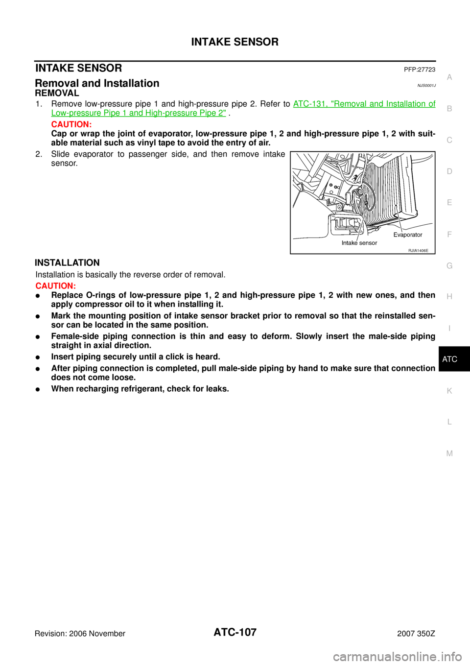
2. Slide evaporator to passenger side, and then remove intake
sensor.
INSTALLATION
Installation is basically the reverse order of removal.
CAUTION:
�Replace O-rings of low-pressure pipe 1, 2 and high-pressure pipe 1, 2 with new ones, and then
apply compressor oil to it when installing it.
�Mark the mounting position of intake sensor bracket prior to removal so that the reinstalled sen-
sor can be located in the same position.
�Female-side piping connection is thin and easy to deform. Slowly insert the male-side piping
straight in axial direction.
�Insert piping securely until a click is heard.
�After piping connection is completed, pull male-side piping by hand to make sure that connection
does not come loose.
�When recharging refrigerant, check for leaks.
RJIA1406E
Page 114 of 142
ATC-114
HEATER & COOLING UNIT ASSEMBLY
Revision: 2006 November2007 350Z
Disassembly and AssemblyNJS0001P
1. Heater pipe grommet 2. Heater core 3. Heater pipe cover
4. Aspirator 5. Aspirator duct 6. Rear foot cover
7. Max. cool door link 8. Max. cool door lever 9. Ventilator door lever
10. Ventilator door link 11. Air mix door motor 12. Intake sensor
13. Foot duct (right) 14. Evaporator cover 15. Evaporator cover adapter
16. Heater pipe bracket 17. Insulator 18. Heater case (right)
SJIA1897E
Page 115 of 142
HEATER & COOLING UNIT ASSEMBLY
ATC-115
C
D
E
F
G
H
I
K
L
MA
B
AT C
Revision: 2006 November2007 350Z
19. Low-pressure pipe 1 20. High-pressure pipe 2 21. O-ring
22. Expansion valve 23. Evaporator 24. Heater case (left)
25. Foot duct (left) 26. Air mix door (slide door) 27. Ventilator door
28. Side link 29. Mode door motor 30. Intake sensor bracket
31. Defroster door 32. Max. cool door 33. Defroster door lever
34. Defroster door link
: N·m (kg-m, in-lb)
: Always replace after every disassembly.
Page 134 of 142

ATC-134
REFRIGERANT LINES
Revision: 2006 November2007 350Z
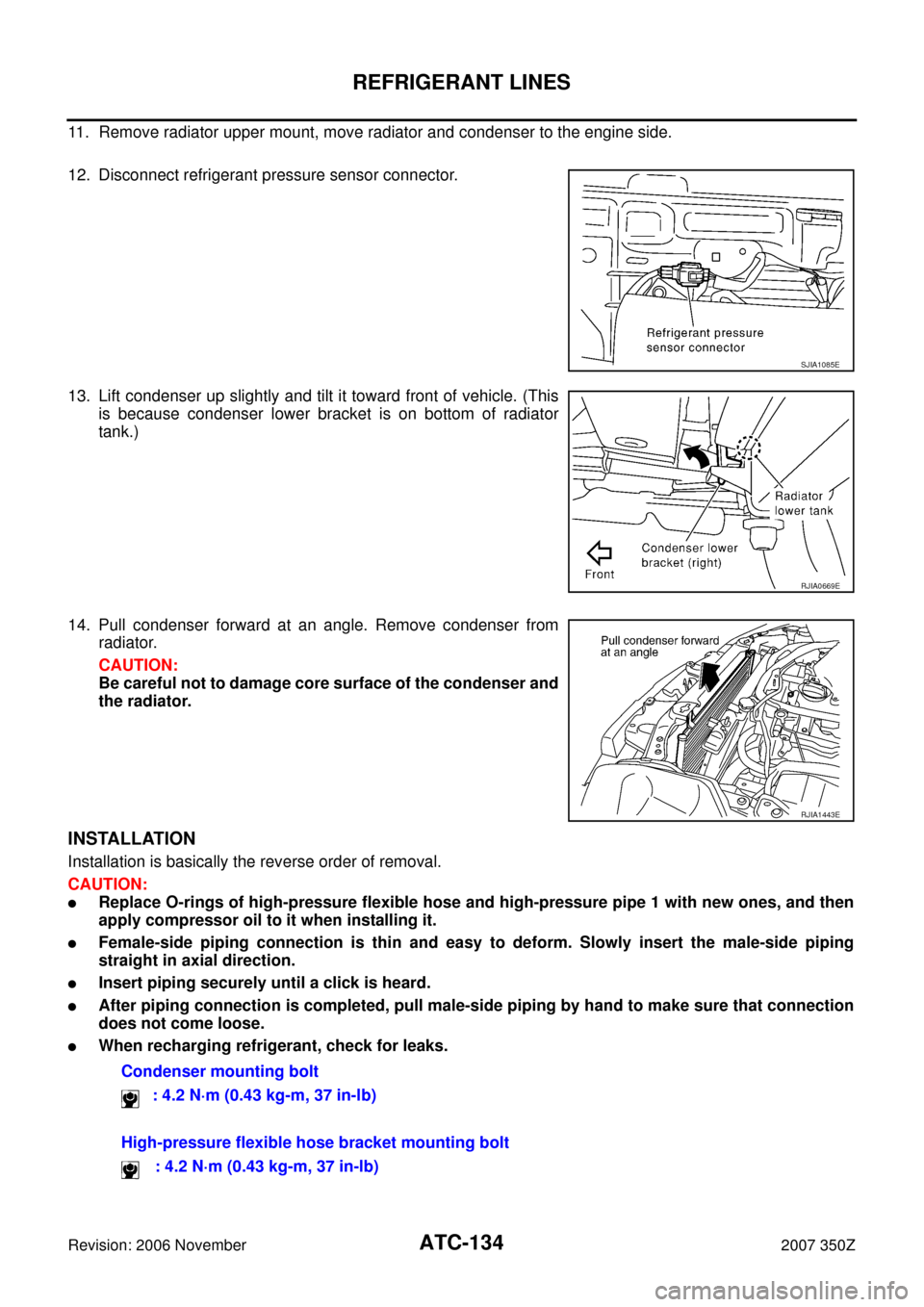
11. Remove radiator upper mount, move radiator and condenser to the engine side.
12. Disconnect refrigerant pressure sensor connector.
13. Lift condenser up slightly and tilt it toward front of vehicle. (This
is because condenser lower bracket is on bottom of radiator
tank.)
14. Pull condenser forward at an angle. Remove condenser from
radiator.
CAUTION:
Be careful not to damage core surface of the condenser and
the radiator.
INSTALLATION
Installation is basically the reverse order of removal.
CAUTION:
�Replace O-rings of high-pressure flexible hose and high-pressure pipe 1 with new ones, and then
apply compressor oil to it when installing it.
�Female-side piping connection is thin and easy to deform. Slowly insert the male-side piping
straight in axial direction.
�Insert piping securely until a click is heard.
�After piping connection is completed, pull male-side piping by hand to make sure that connection
does not come loose.
�When recharging refrigerant, check for leaks.
SJIA1085E
RJIA0669E
RJIA1443E
Condenser mounting bolt
: 4.2 N·m (0.43 kg-m, 37 in-lb)
High-pressure flexible hose bracket mounting bolt
: 4.2 N·m (0.43 kg-m, 37 in-lb)