Page 52 of 116
AV-52
ANTENNA
Revision: 2006 November2007 350Z
ANTENNAPFP:28200
System DescriptionNKS002EG
With the ignition switch in ACC or ON, power is supplied
�through 10A fuse [No. 6, located in the fuse block (J/B)]
�to audio unit terminal 10.
Ground is supplied through the case of the antenna amp.
When the radio switch is turned ON, antenna signal is supplied
�through audio unit terminal 5
�to antenna amp. terminal 1.
Then the antenna amp. is activated.
Antenna signals amplified by the antenna amp. are supplied to the audio unit.
Page 60 of 116
AV-60
NAVIGATION SYSTEM
Revision: 2006 November2007 350Z
Component DescriptionNKS002QA
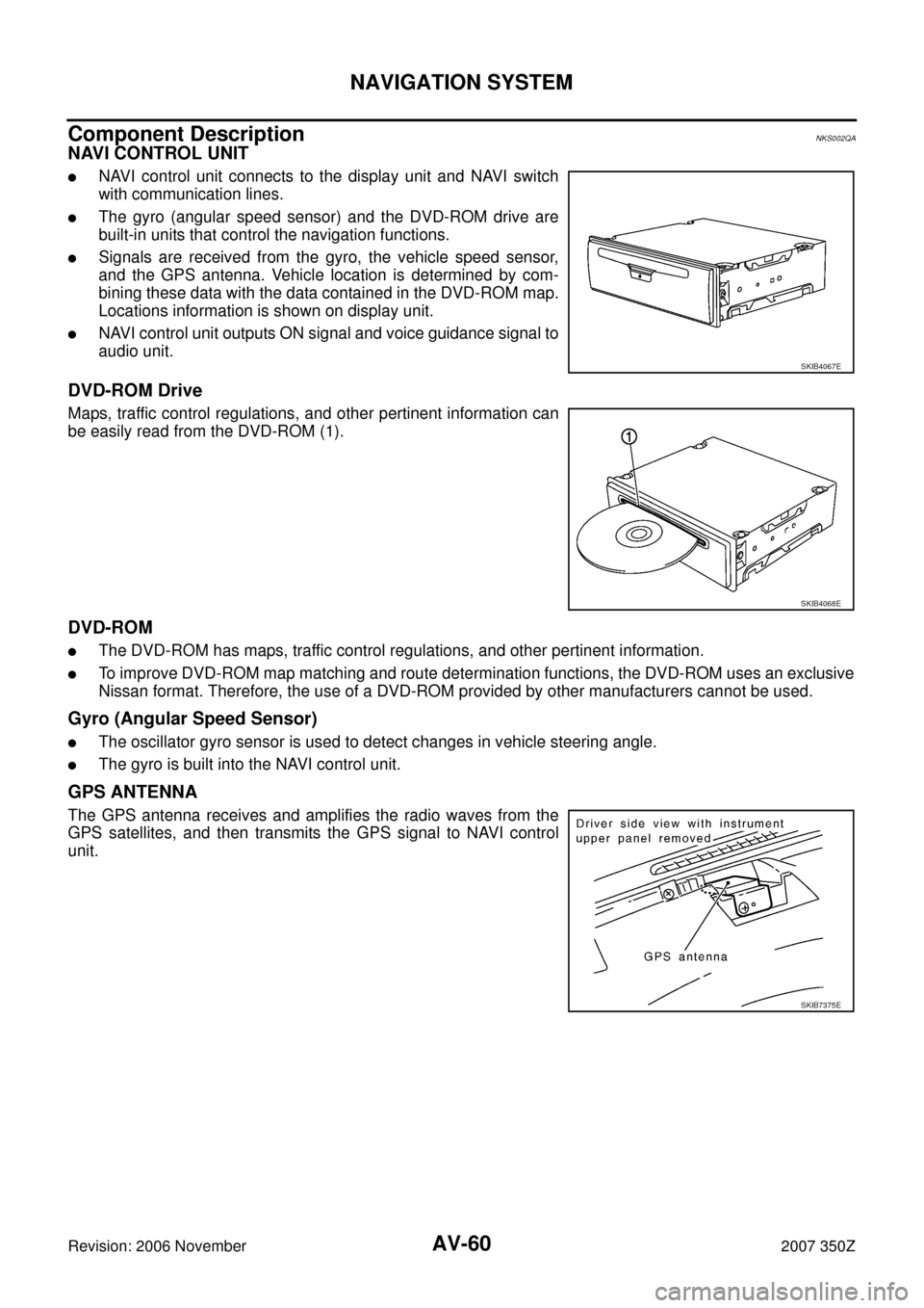
NAVI CONTROL UNIT
�NAVI control unit connects to the display unit and NAVI switch
with communication lines.
�The gyro (angular speed sensor) and the DVD-ROM drive are
built-in units that control the navigation functions.
�Signals are received from the gyro, the vehicle speed sensor,
and the GPS antenna. Vehicle location is determined by com-
bining these data with the data contained in the DVD-ROM map.
Locations information is shown on display unit.
�NAVI control unit outputs ON signal and voice guidance signal to
audio unit.
DVD-ROM Drive
Maps, traffic control regulations, and other pertinent information can
be easily read from the DVD-ROM (1).
DVD-ROM
�The DVD-ROM has maps, traffic control regulations, and other pertinent information.
�To improve DVD-ROM map matching and route determination functions, the DVD-ROM uses an exclusive
Nissan format. Therefore, the use of a DVD-ROM provided by other manufacturers cannot be used.
Gyro (Angular Speed Sensor)
�The oscillator gyro sensor is used to detect changes in vehicle steering angle.
�The gyro is built into the NAVI control unit.
GPS ANTENNA
The GPS antenna receives and amplifies the radio waves from the
GPS satellites, and then transmits the GPS signal to NAVI control
unit.
SKIB4067E
SKIB4068E
SKIB7375E
Page 92 of 116
AV-92
NAVIGATION SYSTEM
Revision: 2006 November2007 350Z
Voice Guidance Is Not HeardNKS000DN
Symptom: Voice guidance does not sound at route guidance.
1. CHECK CONDITION
Turn audio system ON, and check if any sound can be heard from front door speaker.
OK or NG
OK >> GO TO 2.
NG >> Refer to AV- 3 9 , "
Trouble Diagnosis" and repair malfunctioning part.
2. CHECK CONDITION
Turn audio system ON, and check if front door speaker is muted when pressing “VOICE” button during sound-
ing from front door speaker.
Is front door speaker muted?
YES >> GO TO 3.
NO >> GO TO 5.
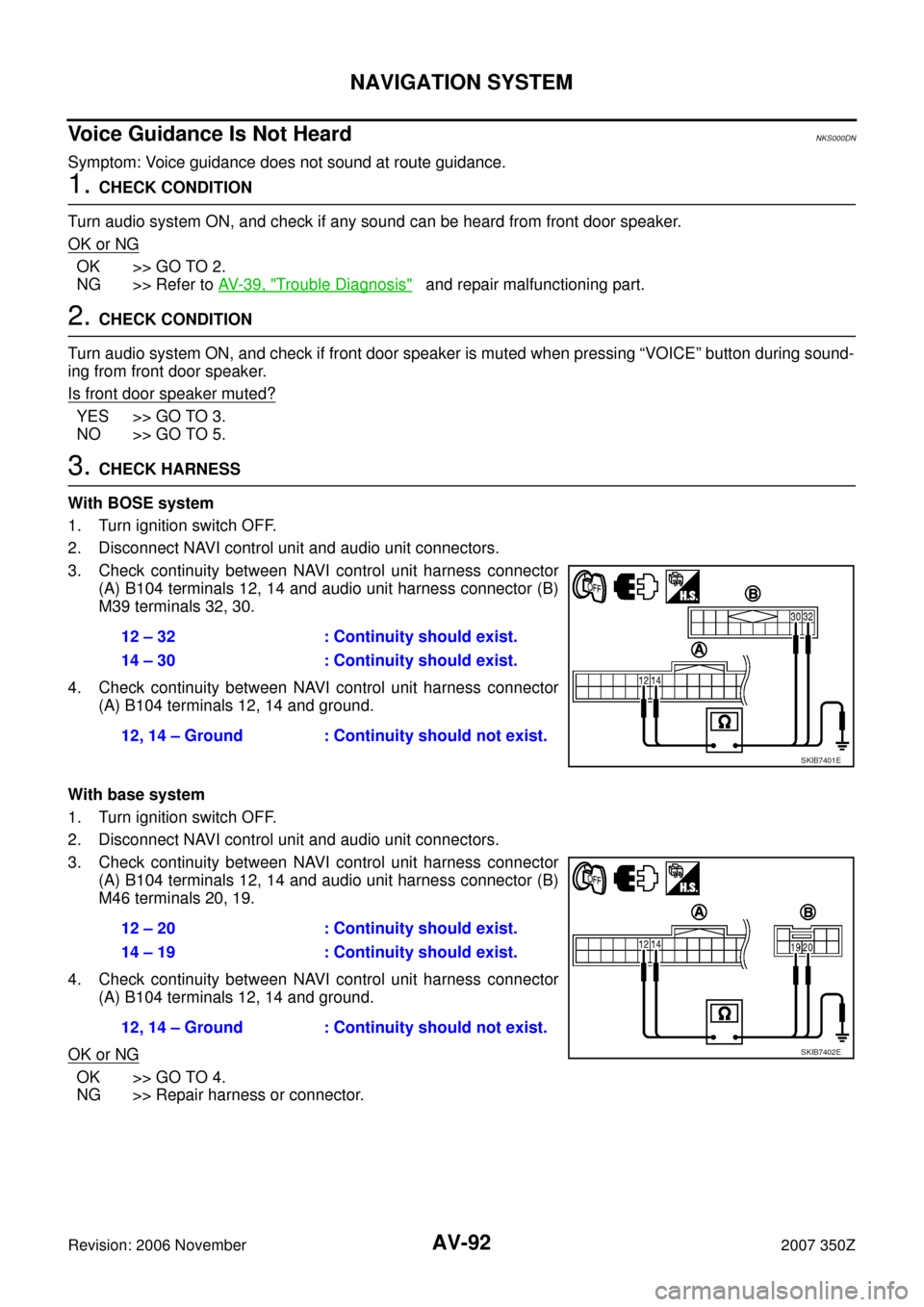
3. CHECK HARNESS
With BOSE system
1. Turn ignition switch OFF.
2. Disconnect NAVI control unit and audio unit connectors.
3. Check continuity between NAVI control unit harness connector
(A) B104 terminals 12, 14 and audio unit harness connector (B)
M39 terminals 32, 30.
4. Check continuity between NAVI control unit harness connector
(A) B104 terminals 12, 14 and ground.
With base system
1. Turn ignition switch OFF.
2. Disconnect NAVI control unit and audio unit connectors.
3. Check continuity between NAVI control unit harness connector
(A) B104 terminals 12, 14 and audio unit harness connector (B)
M46 terminals 20, 19.
4. Check continuity between NAVI control unit harness connector
(A) B104 terminals 12, 14 and ground.
OK or NG
OK >> GO TO 4.
NG >> Repair harness or connector.12 – 32 : Continuity should exist.
14 – 30 : Continuity should exist.
12, 14 – Ground : Continuity should not exist.
SKIB7401E
12 – 20 : Continuity should exist.
14 – 19 : Continuity should exist.
12, 14 – Ground : Continuity should not exist.
SKIB7402E
Page 93 of 116
NAVIGATION SYSTEM
AV-93
C
D
E
F
G
H
I
J
L
MA
B
AV
Revision: 2006 November2007 350Z
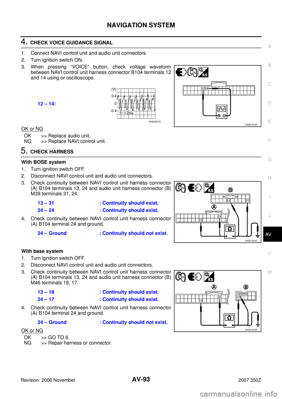
4. CHECK VOICE GUIDANCE SIGNAL
1. Connect NAVI control unit and audio unit connectors.
2. Turn ignition switch ON.
3. When pressing “VOICE” button, check voltage waveform
between NAVI control unit harness connector B104 terminals 12
and 14 using or oscilloscope.
OK or NG
OK >> Replace audio unit.
NG >> Replace NAVI control unit.
5. CHECK HARNESS
With BOSE system
1. Turn ignition switch OFF.
2. Disconnect NAVI control unit and audio unit connectors.
3. Check continuity between NAVI control unit harness connector
(A) B104 terminals 13, 24 and audio unit harness connector (B)
M39 terminals 31, 24.
4. Check continuity between NAVI control unit harness connector
(A) B104 terminal 24 and ground.
With base system
1. Turn ignition switch OFF.
2. Disconnect NAVI control unit and audio unit connectors.
3. Check continuity between NAVI control unit harness connector
(A) B104 terminals 13, 24 and audio unit harness connector (B)
M46 terminals 18, 17.
4. Check continuity between NAVI control unit harness connector
(A) B104 terminal 24 and ground.
OK or NG
OK >> GO TO 6.
NG >> Repair harness or connector.12 – 14:
SKIB7003ESKIB3597E
13 – 31 : Continuity should exist.
24 – 24 : Continuity should exist.
24 – Ground : Continuity should not exist.
SKIB7403E
13 – 18 : Continuity should exist.
24 – 17 : Continuity should exist.
24 – Ground : Continuity should not exist.
SKIB7404E
Page 94 of 116
AV-94
NAVIGATION SYSTEM
Revision: 2006 November2007 350Z
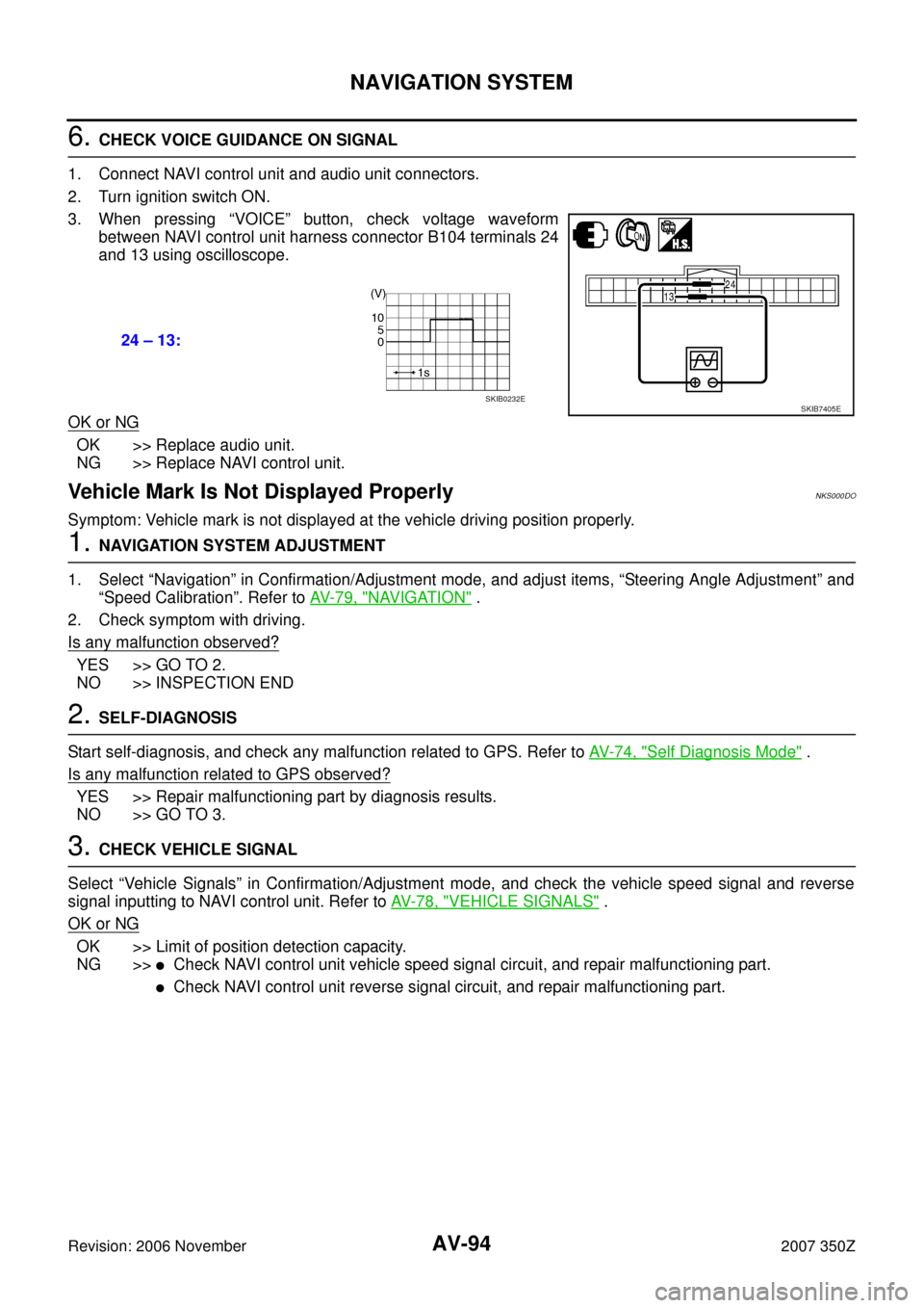
6. CHECK VOICE GUIDANCE ON SIGNAL
1. Connect NAVI control unit and audio unit connectors.
2. Turn ignition switch ON.
3. When pressing “VOICE” button, check voltage waveform
between NAVI control unit harness connector B104 terminals 24
and 13 using oscilloscope.
OK or NG
OK >> Replace audio unit.
NG >> Replace NAVI control unit.
Vehicle Mark Is Not Displayed ProperlyNKS000DO
Symptom: Vehicle mark is not displayed at the vehicle driving position properly.
1. NAVIGATION SYSTEM ADJUSTMENT
1. Select “Navigation” in Confirmation/Adjustment mode, and adjust items, “Steering Angle Adjustment” and
“Speed Calibration”. Refer to AV- 7 9 , "
NAVIGATION" .
2. Check symptom with driving.
Is any malfunction observed?
YES >> GO TO 2.
NO >> INSPECTION END
2. SELF-DIAGNOSIS
Start self-diagnosis, and check any malfunction related to GPS. Refer to AV- 7 4 , "
Self Diagnosis Mode" .
Is any malfunction related to GPS observed?
YES >> Repair malfunctioning part by diagnosis results.
NO >> GO TO 3.
3. CHECK VEHICLE SIGNAL
Select “Vehicle Signals” in Confirmation/Adjustment mode, and check the vehicle speed signal and reverse
signal inputting to NAVI control unit. Refer to AV- 7 8 , "
VEHICLE SIGNALS" .
OK or NG
OK >> Limit of position detection capacity.
NG >>
�Check NAVI control unit vehicle speed signal circuit, and repair malfunctioning part.
�Check NAVI control unit reverse signal circuit, and repair malfunctioning part. 24 – 13:
SKIB7405ESKIB0232E
Page 100 of 116
AV-100
TELEPHONE
Revision: 2006 November2007 350Z
TELEPHONEPFP:28342
System DescriptionNKS0056C
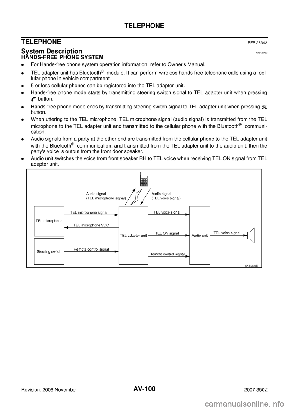
HANDS-FREE PHONE SYSTEM
�For Hands-free phone system operation information, refer to Owner's Manual.
�TEL adapter unit has Bluetooth® module. It can perform wireless hands-free telephone calls using a cel-
lular phone in vehicle compartment.
�5 or less cellular phones can be registered into the TEL adapter unit.
�Hands-free phone mode starts by transmitting steering switch signal to TEL adapter unit when pressing
button.
�Hands-free phone mode ends by transmitting steering switch signal to TEL adapter unit when pressing
button.
�When uttering to the TEL microphone, TEL microphone signal (audio signal) is transmitted from the TEL
microphone to the TEL adapter unit and transmitted to the cellular phone with the Bluetooth
® communi-
cation.
�Audio signals from a party at the other end are transmitted from the cellular phone to the TEL adapter unit
with the Bluetooth
® communication, and transmitted from the TEL adapter unit to the audio unit, then the
party's voice is output from the front door speaker.
�Audio unit switches the voice from front speaker RH to TEL voice when receiving TEL ON signal from TEL
adapter unit.
SKIB9036E
Page 101 of 116
TELEPHONE
AV-101
C
D
E
F
G
H
I
J
L
MA
B
AV
Revision: 2006 November2007 350Z
Component Parts LocationNKS0056D
1. TEL microphone 2. Steering switch 3. TEL antenna
4. TEL adapter unit 5. Audio unit
: Vehicle front
SKIB9135E
Page 111 of 116
TELEPHONE
AV-111
C
D
E
F
G
H
I
J
L
MA
B
AV
Revision: 2006 November2007 350ZSelf-Diagnosis FunctionNKS0056J
�During on board diagnosis the diagnosis function of TEL adapter unit starts with the operation of the steer-
ing switch and performs the diagnosis when ignition switch ACC.
�The on board diagnosis has 3 modes: the self-diagnosis mode that performs the trouble diagnosis, the
speaker adaptation data deleting mode and the hands free phone system initialization mode.
NOTE:
�Perform the diagnosis with the vehicle stopped.
�Perform STEP 2 if necessary.
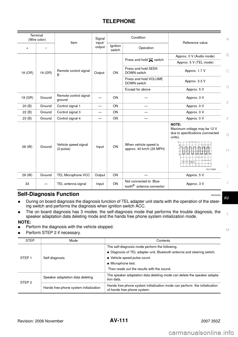
18 (OR) 19 (GR)Remote control signal
BOutput ONPress and hold switchApprox. 0 V (Audio mode)
Approx. 5 V (TEL mode)
Press and hold SEEK
DOWN switchApprox. 1.7 V
Press and hold VOLUME
DOWN switchApprox. 3.3 V
Except for above Approx. 5 V
19 (GR) GroundRemote control signal
ground— ON — Approx. 0 V
20 (B) Ground Control signal 1 — ON — Approx. 0 V
22 (B) Ground Control signal 3 — ON — Approx. 0 V
23 (B) Ground Control signal 4 — ON — Approx. 0 V
28 (W) GroundVehicle speed signal
(2-pulse)Input ONWhen vehicle speed is
approx. 40 km/h (25 MPH)NOTE:
Maximum voltage may be 12 V
due to specifications (connected
units).
29 (W) Ground TEL Microphone VCC Output ON — Approx. 5 V
33 — TEL antenna signal Input ONNot connected to Blue-
tooth
® antenna connectorApprox. 3 V Te r m i n a l
(Wire color)
ItemSignal
input/
outputCondition
Reference value
+–Ignition
switchOperation
ELF1080D
STEP Mode Contents
STEP 1 Self-diagnosisThe self-diagnosis mode perform the following.
�Diagnosis of TEL adapter unit, Bluetooth antenna and steering switch.
�Vehicle speed pulse count.
�Microphone test.
Then reads out the results with the sound.
STEP 2Speaker adaptation data deletingThe speaker adaptation data deleting mode can delete the speaker adapta-
tion data.
Hands free phone system initializationHands free phone system initialization mode can perform the initialization
of hands free phone system.