2007 MITSUBISHI LANCER EVOLUTION ignition
[x] Cancel search: ignitionPage 550 of 1449
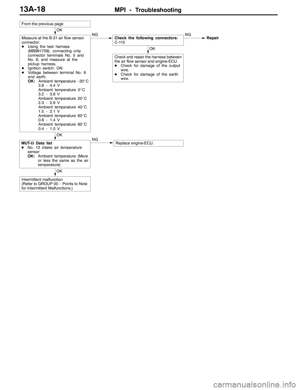
MPI -Troubleshooting13A-18
OK
Intermittent malfunction
(Refer to GROUP 00 - Points to Note
for Intermittent Malfunctions.)
OK
MUT-IIData list
DNo. 13 intake air temperature
sensor
OK:Ambient temperature (More
or less the same as the air
temperature)NGReplace engine-ECU.
OK
Check and repair the harness between
the air flow sensor and engine-ECU.
DCheck for damage of the output
wire.
DCheck for damage of the earth
wire.
OK
Measure at the B-31 air flow sensor
connector.
DUsing the test harness
(MB991709), connecting only
connector terminals No. 5 and
No. 6, and measure at the
pickup harness.
DIgnition switch: ON
DVoltage between terminal No. 6
and earth.
OK:Ambient temperature - 20_C
3.8 - 4.4 V
Ambient temperature 0_C
3.2 - 3.8 V
Ambient temperature 20_C
2.3 - 2.9 V
Ambient temperature 40_C
1.5 - 2.1 V
Ambient temperature 60_C
0.8 - 1.4 V
Ambient temperature 80_C
0.4 - 1.0 VNGCheck the following connectors:
C-115NGRepair
From the previous page
Page 551 of 1449
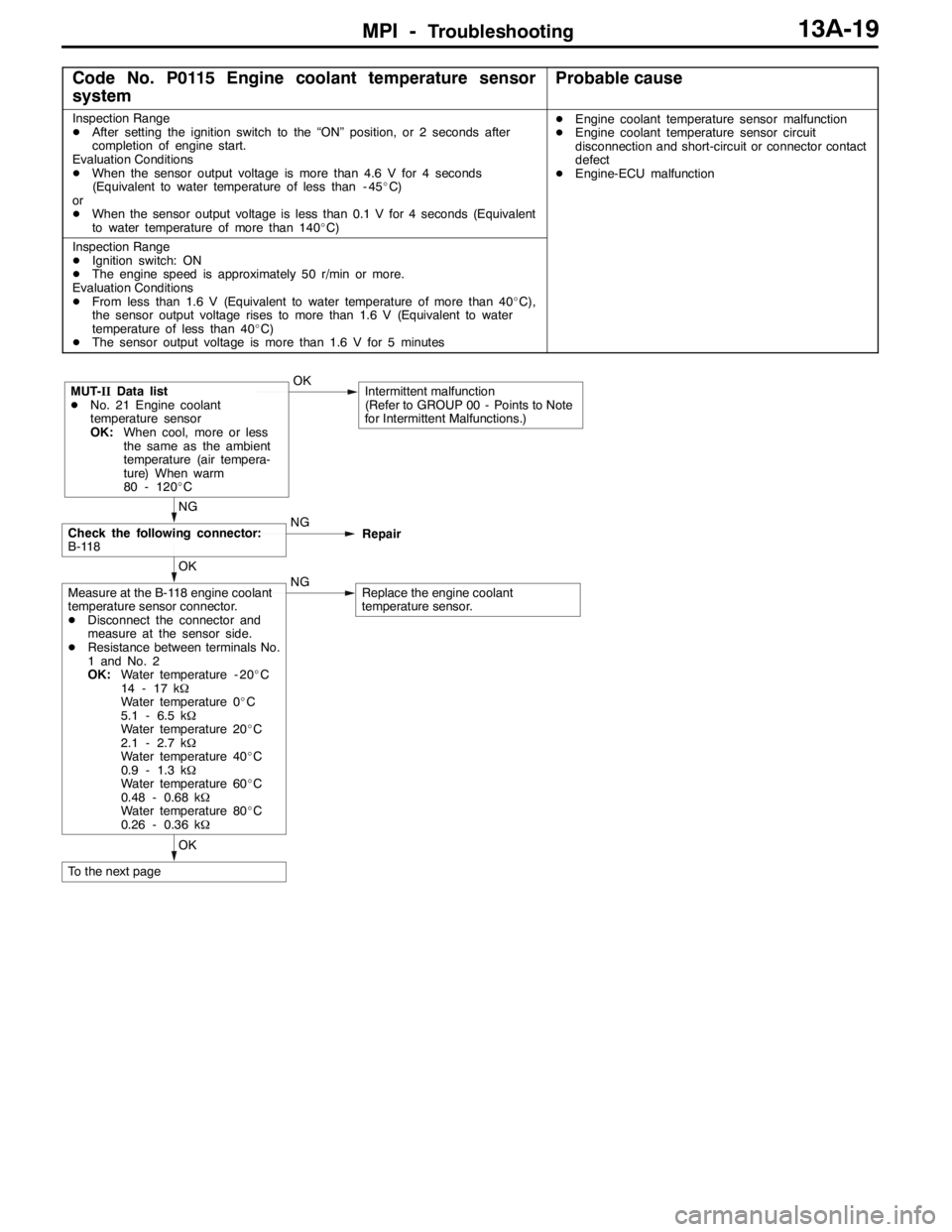
MPI -Troubleshooting13A-19
Code No. P0115 Engine coolant temperature sensor
systemProbable cause
Inspection Range
DAfter setting the ignition switch to the “ON” position, or 2 seconds after
completion of engine start.
Evaluation Conditions
DWhen the sensor output voltage is more than 4.6 V for 4 seconds
(Equivalent to water temperature of less than - 45_C)
or
DWhen the sensor output voltage is less than 0.1 V for 4 seconds (Equivalent
to water temperature of more than 140_C)DEngine coolant temperature sensor malfunction
DEngine coolant temperature sensor circuit
disconnection and short-circuit or connector contact
defect
DEngine-ECU malfunction
Inspection Range
DIgnition switch: ON
DThe engine speed is approximately 50 r/min or more.
Evaluation Conditions
DFrom less than 1.6 V (Equivalent to water temperature of more than 40_C),
the sensor output voltage rises to more than 1.6 V (Equivalent to water
temperature of less than 40_C)
DThe sensor output voltage is more than 1.6 V for 5 minutes
OK
To the next page
OK
Measure at the B-118 engine coolant
temperature sensor connector.
DDisconnect the connector and
measure at the sensor side.
DResistance between terminals No.
1 and No. 2
OK:Water temperature - 20_C
14 - 17 kΩ
Water temperature 0_C
5.1 - 6.5 kΩ
Water temperature 20_C
2.1 - 2.7 kΩ
Water temperature 40_C
0.9 - 1.3 kΩ
Water temperature 60_C
0.48 - 0.68 kΩ
Water temperature 80_C
0.26 - 0.36 kΩNGReplace the engine coolant
temperature sensor.
NG
Check the following connector:
B-118NG
Repair
MUT-IIData list
DNo. 21 Engine coolant
temperature sensor
OK:When cool, more or less
the same as the ambient
temperature (air tempera-
ture) When warm
80 - 120_COKIntermittent malfunction
(Refer to GROUP 00 - Points to Note
for Intermittent Malfunctions.)
Page 552 of 1449
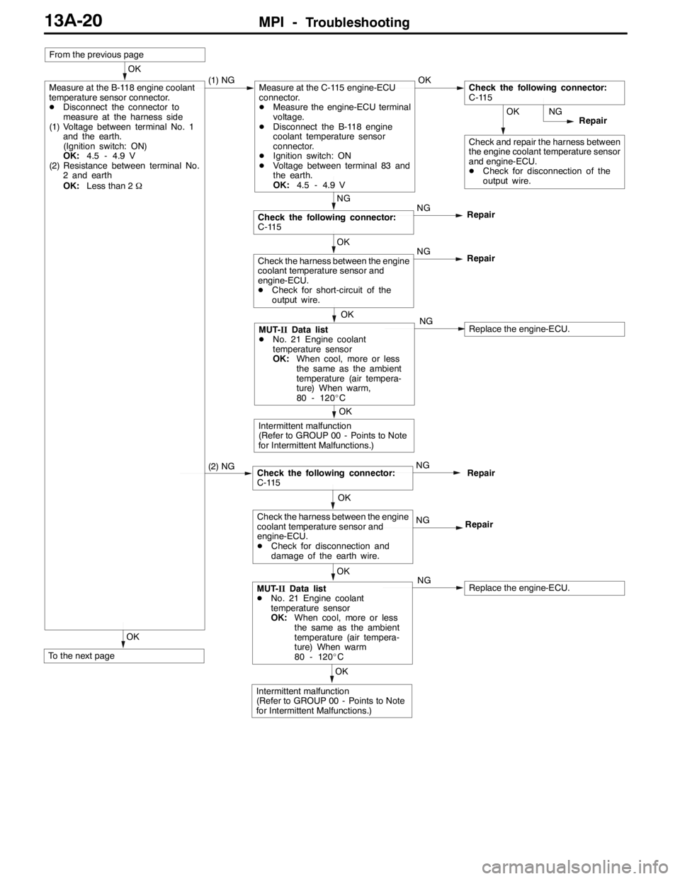
MPI -Troubleshooting13A-20
OK
To the next page
OK
Intermittent malfunction
(Refer to GROUP 00 - Points to Note
for Intermittent Malfunctions.)
OK
MUT-IIData list
DNo. 21 Engine coolant
temperature sensor
OK:When cool, more or less
the same as the ambient
temperature (air tempera-
ture) When warm
80 - 120_CNGReplace the engine-ECU.
OK
Check the harness between the engine
coolant temperature sensor and
engine-ECU.
DCheck for disconnection and
damage of the earth wire.NG
Repair
Check the following connector:
C-115NGRepair (2) NG
OK
Intermittent malfunction
(Refer to GROUP 00 - Points to Note
for Intermittent Malfunctions.)
OK
MUT-IIData list
DNo. 21 Engine coolant
temperature sensor
OK:When cool, more or less
the same as the ambient
temperature (air tempera-
ture) When warm,
80 - 120_CNGReplace the engine-ECU.
OK
Check the harness between the engine
coolant temperature sensor and
engine-ECU.
DCheck for short-circuit of the
output wire.NG
Repair
NG
Check the following connector:
C-115NG
Repair
OK
Check and repair the harness between
the engine coolant temperature sensor
and engine-ECU.
DCheck for disconnection of the
output wire.NG
Repair
OK
Measure at the B-118 engine coolant
temperature sensor connector.
DDisconnect the connector to
measure at the harness side
(1) Voltage between terminal No. 1
and the earth.
(Ignition switch: ON)
OK:4.5 - 4.9 V
(2) Resistance between terminal No.
2 and earth
OK:Less than 2Ω(1) NGMeasure at the C-115 engine-ECU
connector.
DMeasure the engine-ECU terminal
voltage.
DDisconnect the B-118 engine
coolant temperature sensor
connector.
DIgnition switch: ON
DVoltage between terminal 83 and
the earth.
OK:4.5 - 4.9 VOKCheck the following connector:
C-115
From the previous page
Page 553 of 1449
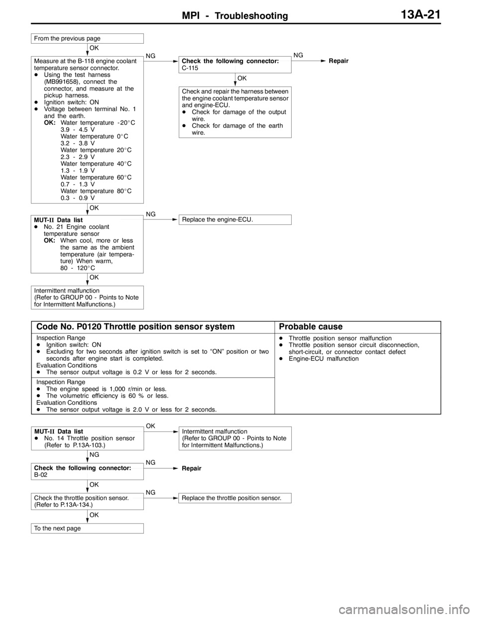
MPI -Troubleshooting13A-21
OK
Intermittent malfunction
(Refer to GROUP 00 - Points to Note
for Intermittent Malfunctions.)
OK
MUT-IIData list
DNo. 21 Engine coolant
temperature sensor
OK:When cool, more or less
the same as the ambient
temperature (air tempera-
ture) When warm,
80 - 120_CNGReplace the engine-ECU.
OK
Check and repair the harness between
the engine coolant temperature sensor
and engine-ECU.
DCheck for damage of the output
wire.
DCheck for damage of the earth
wire.
OK
Measure at the B-118 engine coolant
temperature sensor connector.
DUsing the test harness
(MB991658), connect the
connector, and measure at the
pickup harness.
DIgnition switch: ON
DVoltage between terminal No. 1
and the earth.
OK:Water temperature - 20_C
3.9 - 4.5 V
Water temperature 0_C
3.2 - 3.8 V
Water temperature 20_C
2.3 - 2.9 V
Water temperature 40_C
1.3 - 1.9 V
Water temperature 60_C
0.7 - 1.3 V
Water temperature 80_C
0.3 - 0.9 VNGCheck the following connector:
C-115NG
Repair
From the previous page
Code No. P0120 Throttle position sensor systemProbable cause
Inspection Range
DIgnition switch: ON
DExcluding for two seconds after ignition switch is set to “ON” position or two
seconds after engine start is completed.
Evaluation Conditions
DThe sensor output voltage is 0.2 V or less for 2 seconds.DThrottle position sensor malfunction
DThrottle position sensor circuit disconnection,
short-circuit, or connector contact defect
DEngine-ECU malfunction
Inspection Range
DThe engine speed is 1,000 r/min or less.
DThe volumetric efficiency is 60 % or less.
Evaluation Conditions
DThe sensor output voltage is 2.0 V or less for 2 seconds.
OK
To the next page
OK
Check the throttle position sensor.
(Refer to P.13A-134.)NGReplace the throttle position sensor.
NG
Check the following connector:
B-02NG
Repair
MUT-IIData list
DNo. 14 Throttle position sensor
(Refer to P.13A-103.)OKIntermittent malfunction
(Refer to GROUP 00 - Points to Note
for Intermittent Malfunctions.)
Page 554 of 1449
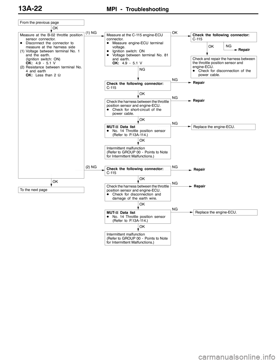
MPI -Troubleshooting13A-22
OK
To the next page
OK
Intermittent malfunction
(Refer to GROUP 00 - Points to Note
for Intermittent Malfunctions.)
OK
MUT-IIData list
DNo. 14 Throttle position sensor
(Refer to P.13A-114.)NGReplace the engine-ECU.
OK
Check the harness between the throttle
position sensor and engine-ECU.
DCheck for disconnection and
damage of the earth wire.NG
Repair
Check the following connector:
C-115NGRepair (2) NG
OK
Intermittent malfunction
(Refer to GROUP 00 - Points to Note
for Intermittent Malfunctions.)
OK
MUT-IIData list
DNo. 14 Throttle position sensor
(Refer to P.13A-114.)NGReplace the engine-ECU.
OK
Check the harness between the throttle
position sensor and engine-ECU.
DCheck for short-circuit of the
power cable.NG
Repair
NG
Check the following connector:
C-115NG
Repair
OK
Check and repair the harness between
the throttle position sensor and
engine-ECU.
DCheck for disconnection of the
power cable.NG
Repair
From the previous page
OK
Measure at the B-02 throttle position
sensor connector.
DDisconnect the connector to
measure at the harness side
(1) Voltage between terminal No. 1
and the earth.
(Ignition switch: ON)
OK:4.9 - 5.1 V
(2) Resistance between terminal No.
4 and earth
OK:Less than 2Ω(1) NGMeasure at the C-115 engine-ECU
connector.
DMeasure engine-ECU terminal
voltage.
DIgnition switch: ON
DVoltage between terminal No. 81
and earth.
OK:4.9 - 5.1 VOKCheck the following connector:
C-115
Page 555 of 1449
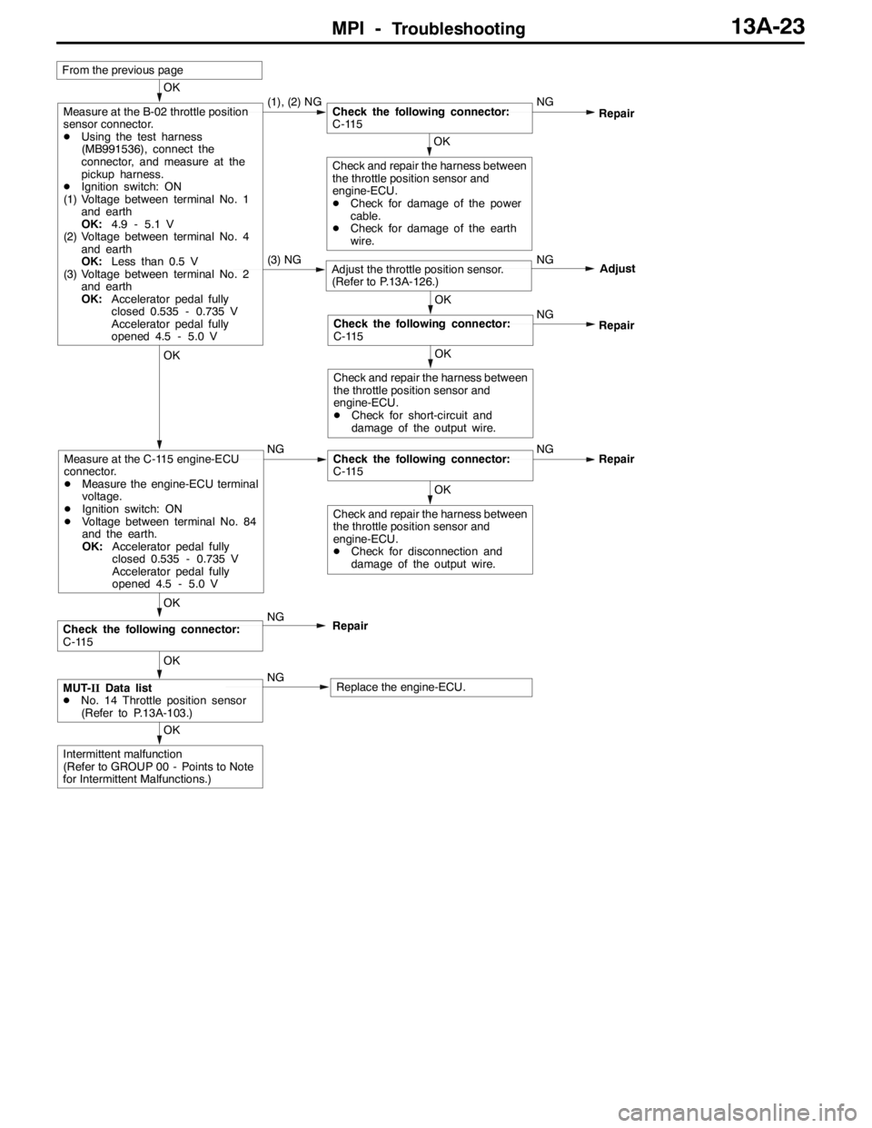
MPI -Troubleshooting13A-23
(3) NGAdjust the throttle position sensor.
(Refer to P.13A-126.)NG
Adjust
OK
Intermittent malfunction
(Refer to GROUP 00 - Points to Note
for Intermittent Malfunctions.)
From the previous page
OK
Check and repair the harness between
the throttle position sensor and
engine-ECU.
DCheck for disconnection and
damage of the output wire.
OK
Measure at the C-115 engine-ECU
connector.
DMeasure the engine-ECU terminal
voltage.
DIgnition switch: ON
DVoltage between terminal No. 84
and the earth.
OK:Accelerator pedal fully
closed 0.535 - 0.735 V
Accelerator pedal fully
opened 4.5 - 5.0 VNGCheck the following connector:
C-115NGRepair
OK
MUT-IIData list
DNo. 14 Throttle position sensor
(Refer to P.13A-103.)NGReplace the engine-ECU.
OK
Check the following connector:
C-115NG
Repair
OK
Check and repair the harness between
the throttle position sensor and
engine-ECU.
DCheck for short-circuit and
damage of the output wire.
OK
Check the following connector:
C-115NG
Repair
OK
Check and repair the harness between
the throttle position sensor and
engine-ECU.
DCheck for damage of the power
cable.
DCheck for damage of the earth
wire.
OK
Measure at the B-02 throttle position
sensor connector.
DUsing the test harness
(MB991536), connect the
connector, and measure at the
pickup harness.
DIgnition switch: ON
(1) Voltage between terminal No. 1
and earth
OK:4.9 - 5.1 V
(2) Voltage between terminal No. 4
and earth
OK:Less than 0.5 V
(3) Voltage between terminal No. 2
and earth
OK:Accelerator pedal fully
closed 0.535 - 0.735 V
Accelerator pedal fully
opened 4.5 - 5.0 V(1), (2) NGCheck the following connector:
C-115NGRepair
Page 558 of 1449
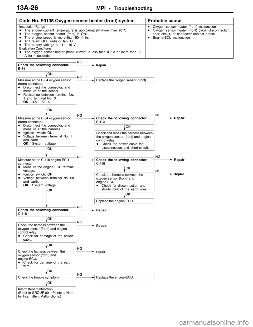
MPI -Troubleshooting13A-26
Code No. P0135 Oxygen sensor heater (front) systemProbable cause
Inspection Range
DThe engine coolant temperature is approximately more than 20_C.
DThe oxygen sensor heater (front) is ON.
DThe engine speed is more than 50 r/min.
DA/C relay: OFF, radiator fan: OFF
DThe battery voltage is 11 - 16 V.
Evaluation Conditions
DThe oxygen sensor heater (front) current is less than 0.2 A or more than 3.5
A for 4 seconds.DOxygen sensor heater (front) malfunction
DOxygen sensor heater (front) circuit disconnection,
short-circuit, or connector contact defect
DEngine-ECU malfunction
OK
Intermittent malfunction
(Refer to GROUP 00 - Points to Note
for Intermittent Malfunctions.)
OK
Check the trouble symptom.NGReplace the engine-ECU.
OK
Check the harness between the
oxygen sensor (front) and
engine-ECU.
DCheck for damage of the earth
wire.NG
repair
OK
Check the harness between the
oxygen sensor (front) and engine
control relay.
DCheck for damage of the power
cable.NG
Repair
OK
Check the following connector:
C-118NG
Repair
OK
Replace the engine-ECU.NG
OK
Check the harness between the
oxygen sensor (front) and
engine-ECU.
DCheck for disconnection and
short-circuit of the earth wire.Repair
OK
Measure at the C-118 engine-ECU
connector.
DMeasure the engine-ECU terminal
voltage.
DIgnition switch: ON
DVoltage between terminal No. 60
and earth.
OK:System voltageNGCheck the following connector:
C-118NG
Repair
OK
Check and repair the harness between
the oxygen sensor (front) and engine
control relay.
DCheck the power cable for
disconnection and short-circuit.
OK
Measure at the B-34 oxygen sensor
(front) connector.
DDisconnect the connector, and
measure at the harness.
DIgnition switch: ON
DVoltage between terminal No. 1
and earth
OK:System voltageNGCheck the following connector:
B-11XNG
Repair
OK
Measure at the B-34 oxygen sensor
(front) connector.
DDisconnect the connector, and
measure at the sensor.
DResistance between terminal No.
1 and terminal No. 3.
OK:4.5 - 8.0ΩNGReplace the oxygen sensor (front).
Check the following connector:
B-34NG
Repair
Page 561 of 1449
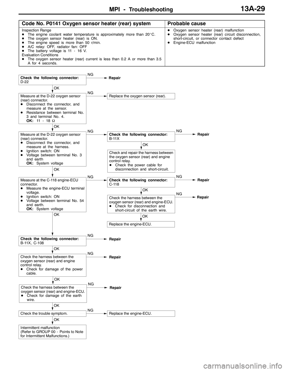
MPI -Troubleshooting13A-29
Code No. P0141 Oxygen sensor heater (rear) systemProbable cause
Inspection Range
DThe engine coolant water temperature is approximately more than 20_C.
DThe oxygen sensor heater (rear) is ON.
DThe engine speed is more than 50 r/min.
DA/C relay: OFF, radiator fan: OFF
DThe battery voltage is 11 - 16 V.
Evaluation Conditions
DThe oxygen sensor heater (rear) current is less than 0.2 A or more than 3.5
A for 4 seconds.DOxygen sensor heater (rear) malfunction
DOxygen sensor heater (rear) circuit disconnection,
short-circuit, or connector contact defect
DEngine-ECU malfunction
OK
Intermittent malfunction
(Refer to GROUP 00 - Points to Note
for Intermittent Malfunctions.)
OK
Check the trouble symptom.NGReplace the engine-ECU.
OK
Check the harness between the
oxygen sensor (rear) and engine-ECU.
DCheck for damage of the earth
wire.NG
Repair
OK
Check the harness between the
oxygen sensor (rear) and engine
control relay.
DCheck for damage of the power
cable.NG
Repair
OK
Check the following connector:
B-11X, C-108NG
Repair
OK
Replace the engine-ECU.NG
OK
Check the harness between the
oxygen sensor (rear) and engine-ECU.
DCheck for disconnection and
short-circuit of the earth wire.Repair
OK
Measure at the C-118 engine-ECU
connector.
DMeasure the engine-ECU terminal
voltage.
DIgnition switch: ON
DVoltage between terminal No. 54
and earth.
OK:System voltageNGCheck the following connector:
C-118NG
Repair
OK
Check and repair the harness between
the oxygen sensor (rear) and engine
control relay.
DCheck the power cable for
disconnection and short-circuit.
OK
Measure at the D-22 oxygen sensor
(rear) connector.
DDisconnect the connector, and
measure at the harness.
DIgnition switch: ON
DVoltage between terminal No. 3
and earth
OK:System voltageNGCheck the following connector:
B-11XNG
Repair
OK
Measure at the D-22 oxygen sensor
(rear) connector.
DDisconnect the connector, and
measure at the sensor.
DResistance between terminal No.
3 and terminal No. 4.
OK:11 - 1 8ΩNGReplace the oxygen sensor (rear).
Check the following connector:
D-22NG
Repair