Page 439 of 1449
ENGINE -Cylinder Head Gasket11A-33
3. In case of not rotating smoothly, remove the fuel high
pressure hose and insert it to the delivery pipe again
after checking damage of the O-ring since there is a
possibility of O-ring engagement.
4. Tighten fuel high pressure hose mounting bolts to the
specified torque.
Tightening Torque: 5.0±1.0 N·m
"DAOIL RETURN PIPE GASKET INSTALLATION
Gasket should be replaced with a new one, and set the convex
part to the position as shown in the illustration for installation.
NOTE
There is no specific direction indicated for installing the
turbocharger side of the oil return pipe gasket.
Convex part
Page 441 of 1449
ENGINE -Timing Belt and Timing Belt B11A-35
12
1314 1516
8.8±1.0 N·m
162±5 N·m 19±3 N·m
(Engine oil)
12. Crank angle sensor
AB""CA13. Crankshaft sprocket
"CA14. Crankshaft sensing blade"BADTiming belt B tension adjustment
"AA15. Timing belt B tensioner
AC""AA16. Timing belt B
REMOVAL SERVICE POINTS
AA"TIMING BELT REMOVAL
1. Rotate the crankshaft clockwise and mate timing marks
with each other to position No.1 cylinder at compression
TDC.
Caution
Ensure that the crankshaft always rotates clockwise.
2. Loosen the mounting bolt of the tensioner pulley and
remove the timing belt.
Caution
When the timing belt is reused, use a chalk to indicate
an arrow of rotation direction on the back of the belt
so that it can be re-assembled in the same direction
as before.
AB"CRANKSHAFT SPROCKET REMOVALTiming Mark
MB991367
Crankshaft
sprocket
MB991385
Page 444 of 1449

ENGINE -Timing Belt and Timing Belt B11A-38
"CACRANKSHAFT SENSING BLADE/CRANKSHAFT
SPROCKET INSTALLATION
1. Clean and degrease the crankshaft sensing blade and
the crankshaft sprocket mounting surfaces of the
crankshaft sprocket and the crankshaft.
2. Install the crankshaft sensing blade and crankshaft
sprocket to the direction as shown in the illustration.
3. Clean the tapped hole of the crankshaft.
4. Position the chamfered side of the washer to the direction
as shown in the illustration and install to the crankshaft
bolt.
5. Apply a small quantity of engine oil to the contact surface
and the threads of crankshaft bolts.
6. Use the special tool to hold the crankshaft sprocket and
tighten the the crankshaft bolt to the specified torque
in the same way as that for removal.
Tightening Torque: 162±5 N·m
"DAAUTO-TENSIONER INSTALLATION
1. If the auto-tensioner rod is being extended, set according
to the following procedure.
(1) Use a press or a vise to compress the rod of the
auto-tensioner slowly and align the mounting hole
A of the rod with the mounting hole B of the tensioner
cylinder.
Caution
Ensure that the operation should be done slowly
because quick compression could damage a rod.
(2) Insert a wire or etc. into the mated mounting hole.
NOTE
If the automatic tensioner is replaced with a new one,
the automatic tensioner comes with a new pin.
2. Install the auto-tensioner to the engine and tighten the
mounting bolt to the specified torque. Do not remove
a wire or a pin before completing timing belt tension
adjustment.
Tightening Torque: 23±3 N·m
"EATENSIONER PULLEY INSTALLATION
Secure the tensioner pulley temporarily as shown in the
illustration.
Clean
Engine Front
Degrease
Crankshaft
Crankshaft
sprocket
Washer
Crankshaft boltCrankshaft sensing
blade
AB
Wire
Tensioner pulley hole
Page 445 of 1449

ENGINE -Timing Belt and Timing Belt B11A-39
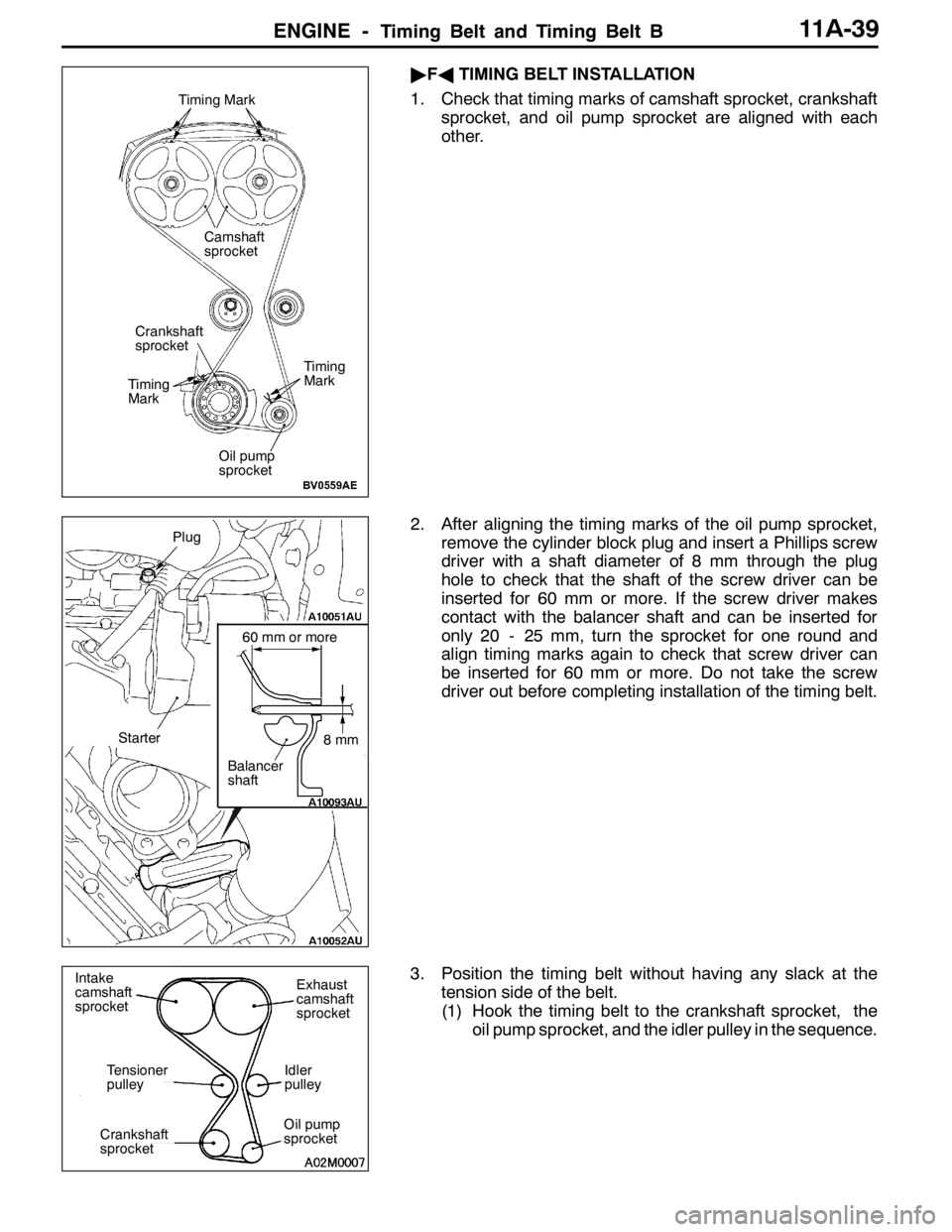
"FATIMING BELT INSTALLATION
1. Check that timing marks of camshaft sprocket, crankshaft
sprocket, and oil pump sprocket are aligned with each
other.
2. After aligning the timing marks of the oil pump sprocket,
remove the cylinder block plug and insert a Phillips screw
driver with a shaft diameter of 8 mm through the plug
hole to check that the shaft of the screw driver can be
inserted for 60 mm or more. If the screw driver makes
contact with the balancer shaft and can be inserted for
only 20 - 25 mm, turn the sprocket for one round and
align timing marks again to check that screw driver can
be inserted for 60 mm or more. Do not take the screw
driver out before completing installation of the timing belt.
3. Position the timing belt without having any slack at the
tension side of the belt.
(1) Hook the timing belt to the crankshaft sprocket, the
oil pump sprocket, and the idler pulley in the sequence.
Timing Mark
Timing
Mark
Timing
Mark
Crankshaft
sprocket
Oil pump
sprocket
Camshaft
sprocket
8mm
60 mm or more
Balancer
shaft
Plug
Starter
Intake
camshaft
sprocketExhaust
camshaft
sprocket
Idler
pulley
Oil pump
sprocketCrankshaft
sprocket
Tensioner
pulley
Page 448 of 1449

ENGINE -Timing belt and timing belt B11A-42
INSPECTION
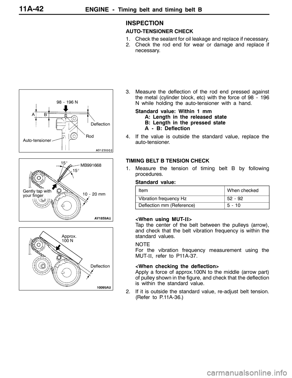
AUTO-TENSIONER CHECK
1. Check the sealant for oil leakage and replace if necessary.
2. Check the rod end for wear or damage and replace if
necessary.
3. Measure the deflection of the rod end pressed against
the metal (cylinder block, etc) with the force of 98 - 196
N while holding the auto-tensioner with a hand.
Standard value: Within 1 mm
A: Length in the released state
B: Length in the pressed state
A - B: Deflection
4. If the value is outside the standard value, replace the
auto-tensioner.
TIMING BELT B TENSION CHECK
1. Measure the tension of timing belt B by following
procedures.
Standard value:
ItemWhen checked
Vibration frequency Hz52 - 92
Deflection mm (Reference)5-10
Tap the center of the belt between the pulleys (arrow),
and check that the belt vibration frequency is within the
standard values.
NOTE
For the vibration frequency measurement using the
MUT-II, refer to P11A-37.
Apply a force of approx.100N to the middle (arrow part)
of pulley shown in the figure, and check that the deflection
is within the standard value.
2. If it is outside the standard value, re-adjust belt tension.
(Refer to P.11A-36.)
AB
Auto-tensioner
98 - 196 N
Deflection
Rod
MB991668
10 - 20 mm
15_
15_
Gently tap with
your finger
Deflection
Approx.
100 N
Page 449 of 1449

ENGINE -Engine Assembly11A-43
ENGINE ASSEMBLY
REMOVAL AND INSTALLATION
Caution
1. If the vehicle is equipped with the Brembo disc brake, during maintenance, take care not to
contact the parts or tools to the caliper because the paint of caliper will be scratched.
2. Tightening sections indicated in the mark (*) should be finally tightened with engine weight
applied on the body after lightly tightening.
Pre-removal and Post-installation Operation
DFuel Outflow Preventive Operation (Refer to GROUP 13A - On-vehicle Service.)
DFuel Leak Check
DRemoval and Installation of Hood (Refer to GROUP 42.)
DRemoval and Installation of Strut Tower Bar (Refer to GROUP 42.)
DRemoval and Installation of Under Cover (Refer to GROUP 51 - Front Bumper.)
DRemoval and Installation of Side Cover.
DDrive Belt Tension Check (Refer to P.11A - 7.)
DAccelerator Cable Adjustment (Refer to GROUP 17 - On-vehicle Service.)
DDrainage and Refilling Engine Oil(Refer to GROUP 12 - On-vehicle Service.)
DDrainage and Refilling of Engine Coolant (Refer to GROUP 14 - On-vehicle Service.)
DAir Cleaner Removal and Installation (Refer to GROUP 15)
DRemoval and Installation of Air Pipe C, Air Pipe B and Air Hose A (Refer to GROUP 15 - Intercooler.)
DBattery and Battery Tray Removal and Installation
DRemoval and Installation of Center Cover (Refer to P.11A - 17.)
DRemoval and Installation of Accelerator Cable (Refer to GROUP 17.)
DRemoval and Installation of Radiator (Refer to GROUP 14.)
DRemoval and Installation of Crossmember Bar (Refer to GROUP 32 - Engine Roll Stopper, Centermember.)
DRemoval and Installation of Front Exhaust Pipe (Refer to GROUP 15.)
DRemoval and Installation of Air Outlet Fitting (Refer to GROUP 15 - Exhaust manifold.)
Page 450 of 1449
ENGINE -Engine Assembly11A-44
1
2
3 4
5
67
8
910
11 12
13
14
26±5 N·m
14±3 N·m
1516
18
5.0±1.0 N·m
1
5.0±1.0 N·m
11±1 N·m
17
Removal steps
1. Ignition coil connector
2. Crank angle sensor connector
3. Oxygen sensor connector
4. Fuel pressure solenoid valve
connector
5. Detonation sensor connector
6. Purge control solenoid valve
connector
7. Throttle position sensor connector
8. Idle speed control servo connector
9. Injector connector
10. Camshaft position sensor connector11. Engine coolant temperature gauge
unit connector
12. Engine coolant temperature sensor
connector
13. Alternator connector
14. EGR solenoid valve connector
15. Secondary air control solenoid valve
connector
16. Engine oil pressure switch
connector
17. Waste gate actuator mounting bolt
AA"18. Drive belt
Page 451 of 1449
ENGINE -Engine Assembly11A-45
67±7 N·m*
23 33
24 29
3031
32
2722
98±10 N·m*5.0±1.0 N·m
(Engine oil)
20
21 19
25
42±2 N·m22±4 N·m
40±5 N·m
42±2 N·m
26
26
2834
22±4 N·m12±2 N·m
19. Brake booster vacuum hose
connection
20. Purge hose connection
21. Power steering oil pressure switch
connector
22. Heat protector
AB"23. Power steering oil pump, bracket and
oil reservoir assembly
24. A/C compressor connector
AB"25. A/C compressor
26. Engine oil cooler tube gasket
27. Engine oil cooler feed hose connection28. Engine oil cooler return hose
connection
29. Heater hose connection
30. Fuel return hose connection
"CA31. Fuel high pressure hose connection
"CA32. O-ring
DTransfer assembly
(Refer to Group 22.)
DTransmission assembly
(Refer to Group 22.)
AC""BA33. Engine mounting bracket and stopper
assembly
AD""AA34. Engine assembly