2007 MITSUBISHI LANCER EVOLUTION power steering
[x] Cancel search: power steeringPage 663 of 1449

MPI -On-vehicle Service13A-131
COMPONENT LOCATION
NameSymbolNameSymbol
A/C relayJFuel pump relay 1, 2Q
A/C switchTFuel pump relay 3H
Air flow sensor (integrated intake air tempera-
ture sensor and barometric pressure sensor)OFuel pump resistorH
Camshaft position sensorNIdle speed control servo (stepper motor)G
Crank angle sensorKIgnition coil (integrated power transister)M
Detonation sensorEInjectorC
Diagnosis connectorSOxygen sensor (front)L
EGR control solenoid valveDOxygen sensor (rear)X
Engine control relayIPower steering fluid pressure switchA
Engine coolant temperature sensorNResistor (for injector)H
Engine warning lamp (check engine lamp)RSecondary air control solenoid valveD
Engine-ECUUThrottle position sensorG
Fan motor relayJVehicle speed sensorF
Fuel pressure control solenoid valveBWaste gate solenoid valveP
ABCDEFGHIJK
LMNOP
QRSTU
Page 768 of 1449

ENGINE ELECTRICAL -Ignition System16-36
12
3
8.8±1.0 N·m
4 5
6 7
8.8±1.0 N·m49±9 N·m
49±9 N·m40±5 N·m 12±2 N·m
22±4 N·m
22±4 N·m
12±2 N·m
22±4 N·m
Removal steps
1. Power steering oil pressure switch
connector
2. Heat protector
AA"3. Power steering oil pump, bracket and
oil reservoir assembly4. Power steering oil pump bracket
5. Crank angle sensor connector
6. Crank angle sensor
7. Connector bracket
REMOVAL SERVICE POINT
AA"POWER STEERING OIL PUMP, BRACKET AND
OIL RESERVOIR ASSEMBLY REMOVAL
Remove the power steering oil pump, bracket and oil reservoir
assembly with the hose attached from the bracket.
NOTE
Tie the removed oil pump with a rope and set aside where
they cannot hinder the removal of the power steering oil pump
bracket.
Page 814 of 1449

MANUAL TRANSMISSION - Troubleshooting
INSPECTION CHART FOR DIAGNOSIS CODES
Diagnosis
code No.Diagnosis itemsReference page
12Power supply voltage (valve power supply) systemopen circuit or short-circuit22A-8
13Fail-safe relay system
21Wheel speed sensor
22Wheel speed sensor
23Wheel speed sensor
24Wheel speed sensor
25Wrong-diameter tire22A-11
26Wheel speed sensor (faulty output signal)22A-13
31Steering wheel sensor
32Steering wheel sensor
33fixed22A-16
34Steering wheel sensor
fixed22A-17
41TPS systemopen circuit or ground22A-18
42short-circuit22A-18
45Pressure sensor systemopen circuit or ground22A-19
46open earth22A-19
47abnormal power supply22A-20
51Longitudinal G sensor systemopen circuit or short-circuit22A-21
52defective sensor22A-22
56Lateral G sensor systemopen circuit or short-circuit22A-23
57defective sensor22A-24
61Stop lamp switch systemopen circuit22A-25
62ACD mode switch systemstuck22A-26
63Parking brake switch systemshort-circuit or not re-
turned to original position22A-27
65ABS monitor systemopen circuit or defective
ABS22A-28
71Proportional valve
GROUP27B
72Directional control valve
GROUP27B.
73Directional control valve
74Proportional valve
Page 819 of 1449

MANUAL TRANSMISSION - Troubleshooting
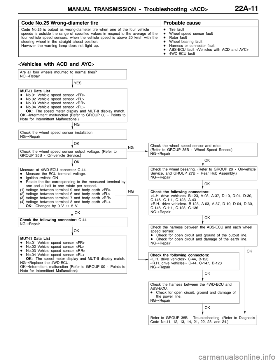
Code No.25 Wrong-diameter tireProbable cause
Code No.25 is output as wrong-diameter tire when one of the four vehicle
speeds is outside the range of specified values in respect to the average of the
four vehicle speed sensors, when the vehicle speed is above 20 km/h with the
steering wheel in the straight ahead position.
However the warning lamp does not light up.DTire fault
DWheel speed sensor fault
DRotor fault
DWheel bearing fault
DHarness or connector fault
DABS-ECU fault
D4WD-ECU fault
OK NG
OK
Check the following connector:C-44
NG→Repair
Check the following connectors:
NG→Repair OKYES
OK
OK
Check the wheel speed sensor and rotor.
(Refer to GROUP 35B - Wheel Speed Sensor.)
NG→Repair
Check the wheel speed sensor output voltage. (Refer to
GROUP 35B - On-vehicle Service.)OK
Check the wheel speed sensor installation.
NG→Repair
NG
OK
Check the wheel beearing. (Refer to GROUP 26 - On-vehicle
Service, and GROUP 27B - Rear Hub Assembly.)
NG→Repair
OK
Check the following connectors:
C-146, C-111, C-128, A-43
C-146, C-111, C-128, C-136
NG→Repair NG
MUT-IIData List
DNo.01 Vehicle speed sensor
DNo.02 Vehicle speed sensor
DNo.03 Vehicle speed sensor
DNo.04 Vehicle speed sensor
OK:The speed meter display and MUT-IIdisplay match.
OK→Intermittent malfunction (Refer to GROUP 00 - Points to
Note for Intermittent Malfunctions.)
Measure at 4WD-ECU connector C-44.
DMeasure the ECU terminal voltage.
DIgnition switch: ON
DRotate the tire corresponding to the measured terminal by
one and a half to one rotate per second.
(1) Voltage between terminal 9 and body earth
(2) Voltage between terminal 6 and body earth
(3) Voltage between terminal 7 and body earth
(4) Voltage between terminal 8 and body earth
OK:Changes by 0 V↔5V.
MUT-IIData List
DNo.01 Vehicle speed sensor
DNo.02 Vehicle speed sensor
DNo.03 Vehicle speed sensor
DNo.04 Vehicle speed sensor
OK:The speed meter display and MUT-IIdisplay match.
NG→Replace the 4WD-ECU.
OK→Intermittent malfunction (Refer to GROUP 00 - Points to
Note for Intermittent Malfunctions)
Refer to GROUP 35B - Troubleshooting. (Refer to Diagnosis
Code No.11, 12, 13, 14, 21, 22, 23, and 24.)
Are all four wheels mounted to normal tires?
NO→Repair
Check the harness between the ABS-ECU and each wheel
speed sensor.
DCheck for open circuit and ground of the output line.
DCheck for open circuit and damage of the earth line.
NG→Repair
OK
Check the harness between the 4WD-ECU and
ABS-ECU.
DCheck for open circuit, ground and damage of
the power line.
NG→RepairOK
Page 823 of 1449

MANUAL TRANSMISSION - Troubleshooting
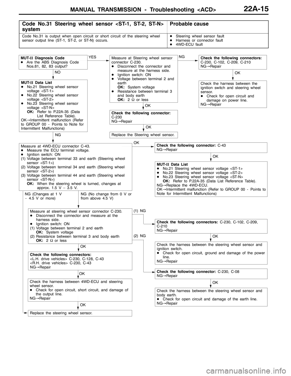
Code No.31 Steering wheel sensor
systemProbable cause
Code No.31 is output when open circuit or short circuit of the steering wheel
sensor output line (ST-1, ST-2, or ST-N) occurs.DSteering wheel sensor fault
DHarness or connector fault
D4WD-ECU fault
OK NG NO
OK
MUT-IIData List
DNo.21 Steering wheel sensor
voltage
DNo.22 Steering wheel sensor
voltage
DNo.23 Steering wheel sensor
voltage
OK:Refer to P.22A-35 (Data
List Reference Table).
OK→Intermittent malfunction (Refer
to GROUP 00 - Points to Note for
Intermittent Malfunctions)
Check the following connector:C-43
NG→Repair YES
MUT-IIDiagnosis Code
DAre the ABS Diagnosis Code
Nos.81, 82, 83 output?
MUT-IIData List
DNo.21 Steering wheel sensor voltage
DNo.22 Steering wheel sensor voltage
DNo.23 Steering wheel sensor voltage
OK:Refer to P.22A-35 (Data List Reference Table).
NG→Replace the 4WD-ECU.
OK→Intermittent malfunction (Refer to GROUP 00 - Points to
Note for Intermittent Malfunctions)
NG (No change from 0 V or
from above 4.5 V)
Measure at 4WD-ECU connector C-43.
DMeasure the ECU terminal voltage.
DIgnition switch: ON
(1) Voltage between terminal 33 and earth (Steering wheel
sensor
(2) Voltage between terminal34and earth (Steering wheel
sensor
(3) Voltage between terminal44 andearth (Steering wheel
sensor
OK:When the steering wheel is turned, changes at
approx. 1.5 V – 3.5 V.
(1) NG
NG (Changes at 1 V
- 4.5 V or more)
OK
Check the harness between the steering wheel sensor and
ignition switch.
DCheck for open circuit, ground and damage of the power
line.
NG→Repair
Check the following connectors:C-230, C-102, C-209,
C-210
NG→Repair
OKOK
Check the following connectors:
NG→Repair
OK
Check the harness between 4WD-ECU and steering
wheel sensor.
DCheck for open circuit, short circuit, and damage of
the output line.
NG→Repair
Replace the steering wheel sensor.
Replace the Steering wheel sensor.
OK
OK
Check the following connector:
C-230
NG→RepairNG
Measure at Steering wheel sensor
connector C-230.
DDisconnect the connector and
measure at the harness side.
DIgnition switch: ON
DVoltage between terminal 2 and
earth
OK:System voltage
DResistance between terminal 3
and body earth
OK:2Ωor less
OK
Check the following connectors:
C-230, C-102, C-209, C-210
NG→Repair
Check the harness between the
ignition switch and steering wheel
sensor.
DCheck for open circuit and
damage on power line.
NG→Repair
(2) NG
OK
Check the harness between the steering wheel sensor and
body earth.
DCheck for open circuit and damage of the earth line.
NG→Repair
Check the following connector:C-230, C-08
NG→Repair
Measure at steering wheel sensor connector C-230.
DDisconnect the connector and measure at the
harness side.
DIgnition switch: ON
(1) Voltage between terminal 2 and earth
OK:System voltage
(2) Resistance between terminal 3 and body earth
OK:2Ωor less
Page 844 of 1449

MANUAL TRANSMISSION - Troubleshooting
Item
no.Normal conditions Check condition Check item
19Pressure sensor power
supplyIgnition switch: ONApprox.5 V
20Valve power supplyIgnition switch: ONSystem voltage
21Steering wheel sensor
voltage
are displayed alter-
nately.
22Steering wheel sensor
voltage
are displayed alter-
nately.
23Steering wheel sensor
ltSTN
Ignition switch: ONSteering wheel: Neutral1-2Vg
voltage
g
Steering wheel: Turn2.5 - 4.5 V
51Idle switchIgnition switch: ONAccelerator pedal: Full
closedON
Accelerator pedal: PressOFF
52Steering wheel sensor
STN
Ignition switch: ONsteering wheel: NeutralONg
g
Steering wheel: Turn from
the neutral positionOFF
53Steering wheel sensor
played alternaltely.
54Steering wheel sensor
played alternately
55Steering wheel sensor
learning
tral position learning exe-
cutedON
Steering wheel sensor neu-
tral position learning unex-
ecutedOFF
56Stop lamp switchIgnition switch: ONBrake pedal: DepressONppg
Engine: StoppedBrake pedal: ReleaseOFF
57Motor monitorElectric pump motor is currently operatingON
Electric pump motor is currently not operatingOFF
58Oil pressure stateElectric pump motor is currently operatingLOWp
Electric pump motor is currently not operatingHIGH
59Directional valve
Ri ht
AYC clutch right side is currently operatingON
60Directional valve
Lft
AYC clutch left side is currently operatingON
61ABS monitorABS is currently operatingON
ABS is currently not operatingOFF
62Parking brake switchIgnition switch: ONParking brake lever: PullONgg
Engine:StoppedParking brake lever: Re-
leaseOFF
63ACD mode switchIgnition switch: ONACD mode switch: PressONg
Engine:StoppedACD mode switch: ReleaseOFF
Page 847 of 1449

MANUAL TRANSMISSION - Troubleshooting
Termi-
nal no.Normal state Check condition Check item
24*2Longitudinal G sensor
earth, lateral G sensor
earthAny time1 V or less
26ECU earthAny time1 V or less
31ECU backup power
supplyAny timeSystem voltage
32Pressure sensorIgnition switch: ON0.5 - 1.5 V
33Steering wheel sensor
4.5 V flushing
34Steering wheel sensor
4.5 V flushing
35Diagnosis data input/
output--
36Idle switchIgnition switch: ONAccelerator pedal: Full closed1 V or lessg
Accelerator pedal: Depress4.5 - 5.0 V
37Parking brake switchIgnition switch: ONParking brake lever: Pull1 V or lessgg
Parking brake lever: ReleaseSystem voltage
38Stop lamp switchIgnition switch: ONBrake pedal: DepressSystem voltageppg
Brake pedal: Release1 V or less
39TPSIgnition switch: ONAccelerator pedal: Full closed0.5 - 0.7 Vg
Accelerator pedal: Full throttle4.5 - 5.5 V
40ACD mode indicator
lamp
TARMAC0V
p
ACD mode indicator lamp position:
Except for aboveApprox. 10.5 V
42ECU earthAny time1 V or less
43Pressure sensor earthAny time1 V or less
44Steering wheel sensor
STN
Ignition switch: ONSteering wheel: Neutral1-2Vg
g
Steering wheel: Turn from the
neutral position2.5 - 4.5 V
46Diagnosis control--
47ACD mode switchIgnition switch: ONSwitch: PressSystem voltageg
Switch: Release0V
49*1ABS monitorWith ABS not activeSystem voltage
With ABS active1.5 V or less
50*2EarthAny time1 V or less
51ACD mode indicator
lamp
SNOW0V
p
ACD mode indicator lamp position:
Except for aboveApprox. 10.5 V
52ACD mode indicator
lamp
GRAVEL0V
p
ACD mode indicator lamp position:
Except for aboveApprox. 10.5 V
Page 1017 of 1449

POWER PLANT MOUNT - General Information/Special Tool32-3
Front roll stopper Front roll mount bracketRear roll stopper Rear roll mount bracket
Crossmember
Crossmember bar
Centermember
SPECIAL TOOL
ToolNumberNameUse
MB990635,
MB991113 or
MB991406
Steering linkage
pullerTie rod end disconnection