2007 MITSUBISHI LANCER EVOLUTION oil temperature
[x] Cancel search: oil temperaturePage 849 of 1449

MANUAL TRANSMISSION - On-vehicle Service22A-41
4. Fill with specified oil till the level comes to the lower portion
of oil filler plug hole.
Specified transfer oil:
MITSUBISHI Genuine Gear Oil Part No.8149630
EX, CASTROL HYPOY LS (GL-5, SAE 90),
SHELL-LSD (GL-5, SAE 80W - 90) or equivalent
Quantity:
0.55 L
0.6 L
5. Tighten the oil filler plug to the specified torque.
Tightening torque: 32±2 N·m
FLUID CHECK
1. Remove the maintenance lid located in the luggage
compartment.
2.
If the vehicle has been run, leave it for 90 min. or more
in an ordinary temperature (10_C–30_C) to allow the
accumulator internal pressure to drop.
NOTE
If the ambient temperature is 10_C or less, allow more
time to leave the vehicle to stand idle.
Set the MUT-IIto the 16-pin diagnosis connector. Turn ON
the ignition switch, perform MUT-IIactuator test (Item
No.03), forcibly drive the hydraulic unit and remove the
pressure in the accumulator.
Caution
Turn the ignition switch to the “LOCK”(OFF) position
before connecting or disconnecting the MUT-II.
NOTE
(1) In the actuator test (Item No. 03: Oil Level Check
Mode), the directional valve of the hydraulic unit is
moved to the left and right for 20 times, and then
the differential is cleared automatically. Drive can also
be cleared forcibly using the Clear key of the MUT-II.
(2) If the function has been stopped by fail-safe, the
hydraulic unit cannot be cleared forcibly.
3. Check that the fluid level in the oil reservoir is in the
range between MAX and MIN.
4. If the fluid level is lower than MIN, add the specified
fluid.
Specified fluid: Dia Queen ATF SP III
5. Reinstall the maintenance lid.
Page 965 of 1449
REAR AXLE -On-vehicle Service27B-19
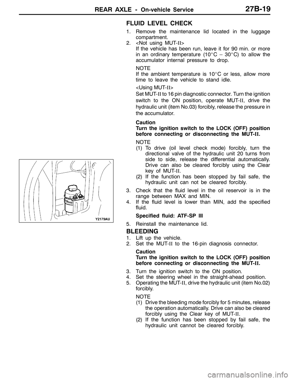
FLUID LEVEL CHECK
1. Remove the maintenance lid located in the luggage
compartment.
2.
If the vehicle has been run, leave it for 90 min. or more
in an ordinary temperature (10_C–30_C) to allow the
accumulator internal pressure to drop.
NOTE
If the ambient temperature is 10_C or less, allow more
time to leave the vehicle to stand idle.
Set MUT-IIto 16 pin diagnostic connector. Turn the ignition
switch to the ON position, operate MUT-II, drive the
hydraulic unit (item No.03) forcibly, release the pressure in
the accumulator.
Caution
Turn the ignition switch to the LOCK (OFF) position
before connecting or disconnecting the MUT-II.
NOTE
(1) To drive (oil level check mode) forcibly, turn the
directional valve of the hydraulic unit 20 turns from
side to side, release the differential automatically.
Drive can also be cleared forcibly using the Clear
key of MUT-II.
(2) If the function has been stopped by fail safe, the
hydraulic unit can not be cleared forcibly.
3. Check that the fluid level in the oil reservoir is in the
range between MAX and MIN.
4. If the fluid level is lower than MIN, add the specified
fluid.
Specified fluid: ATF-SP III
5. Reinstall the maintenance lid.
BLEEDING
1. Lift up the vehicle.
2. Set the MUT-IIto the 16-pin diagnosis connector.
Caution
Turn the ignition switch to the LOCK (OFF) position
before connecting or disconnecting the MUT-II.
3. Turn the ignition switch to the ON position.
4. Set the steering wheel in the straight-ahead position.
5. Operating the MUT-II, drive the hydraulic unit (item No.02)
forcibly.
NOTE
(1) Drive the bleeding mode forcibly for 5 minutes, release
the operation automatically. Drive can also be cleared
forcibly using the Clear key of MUT-II.
(2) If the function has been stopped by fail safe, the
hydraulic unit cannot be cleared forcibly.
Page 1072 of 1449
ABS <4WD> -General Information35B-2
GENERAL INFORMATION
ABS has been adopted as optional equipment in
RS-IIto maintain directional stability and steering
performance during sudden braking or braking on
slippery road surfaces.
The ABS control method is a 4-sensor, 4-channel
method which provides independent control for all
wheels.
Following system for Lancer EVOLUTION-VII has
been modified from Lancer EVOLUTION-VI Tommi
Makinen Edition.DBy adding lateral G sensor, longitudinal G
sensor and steering wheel sensor, optimized
ABS control at the time of cornering.
DBy inputting parking brake switch signal to
ABS-ECU with pulling parking brake lever, ABS
control has been optimized.
DABS-ECU outputs ABS signal to 4WD-ECU.
DG sensor (lateral), steering wheel sensor and
parking brake switch have been added to the
diagnosis and service data.
DABS-ECU connector has been changed.
EBD CONTROL
In ABS, electronic control method is used by which
the rear wheel brake hydraulic pressure during
braking is regulated by rear wheel control solenoid
valves in accordance with the vehicle’s rate of
deceleration and the front and rear wheel slippage
which are calculated from the each wheel speed
sensor’s signal. EBD control is a control system
which provides a high level of control for both vehicle
braking force and vehicle stability. The system has
the following features:
DBecause the system provides the optimum rear
wheel braking force regardless of the vehicleladen condition and the condition of the road
surface, the system reduces the required pedal
depression force, particularly when the vehicle
is heavily laden or driving on road surfaces
with high frictional coefficients.
DBecause the duty placed on the front brakes
has been reduced, the increases in pad
temperature can be controlled to improve the
wear resistance characteristics of the pad,
during front brakes applying.
DControl valves such as the proportioning valve
are no longer required.
SPECIFICATIONS
ItemSpecifications
ABS control method4-sensor, 4-channel
No. of ABS rotor teethFront43
Rear43
ABS speed sensorTypeMagnet coil typep
Gap between sensor and rotor mm0.85
Page 1123 of 1449
STEERING -On-vehicle Service37A-9
POWER STEERING FLUID LEVEL CHECK
1. Park the vehicle on a flat, level surface, start the engine,
and then turn the steering wheel several times to raise
the temperature of the fluid to approximately 50 - 60_C.
2. With the engine running, turn the wheel all the way to
the left and right several times.
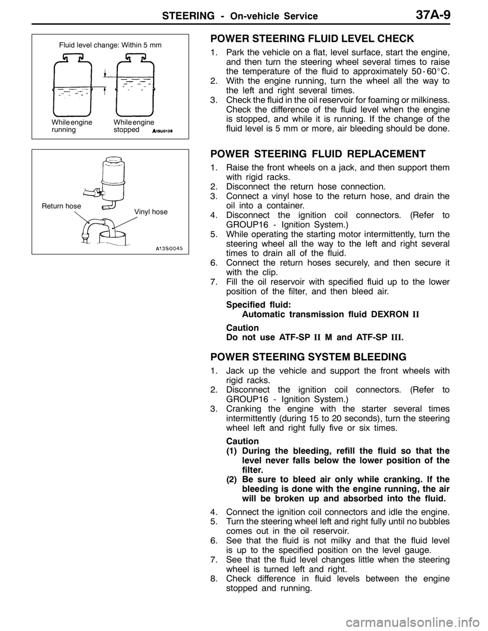
3. Check the fluid in the oil reservoir for foaming or milkiness.
Check the difference of the fluid level when the engine
is stopped, and while it is running. If the change of the
fluid level is 5 mm or more, air bleeding should be done.
POWER STEERING FLUID REPLACEMENT
1. Raise the front wheels on a jack, and then support them
with rigid racks.
2. Disconnect the return hose connection.
3. Connect a vinyl hose to the return hose, and drain the
oil into a container.
4. Disconnect the ignition coil connectors. (Refer to
GROUP16 - Ignition System.)
5. While operating the starting motor intermittently, turn the
steering wheel all the way to the left and right several
times to drain all of the fluid.
6. Connect the return hoses securely, and then secure it
with the clip.
7. Fill the oil reservoir with specified fluid up to the lower
position of the filter, and then bleed air.
Specified fluid:
Automatic transmission fluid DEXRONII
Caution
Do not use ATF-SPIIM and ATF-SPIII.
POWER STEERING SYSTEM BLEEDING
1. Jack up the vehicle and support the front wheels with
rigid racks.
2. Disconnect the ignition coil connectors. (Refer to
GROUP16 - Ignition System.)
3. Cranking the engine with the starter several times
intermittently (during 15 to 20 seconds), turn the steering
wheel left and right fully five or six times.
Caution
(1) During the bleeding, refill the fluid so that the
level never falls below the lower position of the
filter.
(2) Be sure to bleed air only while cranking. If the
bleeding is done with the engine running, the air
will be broken up and absorbed into the fluid.
4. Connect the ignition coil connectors and idle the engine.
5. Turn the steering wheel left and right fully until no bubbles
comes out in the oil reservoir.
6. See that the fluid is not milky and that the fluid level
is up to the specified position on the level gauge.
7. See that the fluid level changes little when the steering
wheel is turned left and right.
8. Check difference in fluid levels between the engine
stopped and running.
Fluid level change: Within 5 mm
While engine
runningWhile engine
stopped
Return hose
Vinyl hose
Page 1124 of 1449
STEERING -On-vehicle Service37A-10
9. If the level changes more than 5 mm, the air is badly
bled. So, bleed air again.
Caution
(1) If the fluid level rises suddenly after the engine
is stopped, the bleeding is incomplete.
(2) Incomplete bleeding causes abnormal noises
from the pump and the flow-control valve. This
could lessen the life of the pump and the other
parts.
OIL PUMP PRESSURE TEST
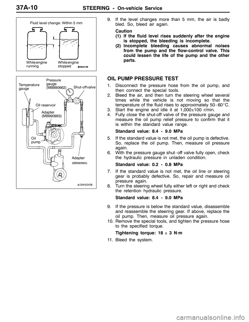
1. Disconnect the pressure hose from the oil pump, and
then connect the special tools.
2. Bleed the air, and then turn the steering wheel several
times while the vehicle is not moving so that the
temperature of the fluid rises to approximately 50 - 60_C.
3. Start the engine and idle it at 1,000±100 r/min.
4. Fully close the shut-off valve of the pressure gauge and
measure the oil pump relief pressure to confirm that it
is within the standard value range.
Standard value: 8.4 - 9.0 MPa
5. If the standard value is not met, the oil pump is defective.
So, replace the oil pump. Then, measure oil pressure
again.
6. With the pressure gauge shut - off valve fully open, check
the hydraulic pressure in unladen condition.
Standard value: 0.2 - 0.8 MPa
7. If the standard value is not met, the oil line or steering
gear is probably defective. So, repair and measure oil
pressure again.
8. Turn the steering wheel fully either left or right and check
the retention hydraulic pressure.
Standard value: 8.4 - 9.0 MPa
9. If the pressure is below the standard value, disassemble
and reassemble the steering gear. If above, replace the
oil pump. Then, measure oil pressure again.
10. Remove the special tools, and tighten the pressure hose
to the specified torque.
Tightening torque: 18±3 N·m
11. Bleed the system.
Fluid level change: Within 5 mm
While engine
runningWhile engine
stopped
Temperature
gaugePressure
gauge
(MB990662)Shut-off valve
Oil
pumpOil reservoir
Adapter
(MB990994)
Adapter
(MB990993)
Page 1125 of 1449
STEERING -On-vehicle Service37A-11
POWER STEERING OIL PRESSURE SWITCH
CHECK
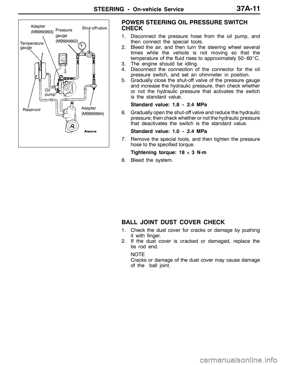
1. Disconnect the pressure hose from the oil pump, and
then connect the special tools.
2. Bleed the air, and then turn the steering wheel several
times while the vehicle is not moving so that the
temperature of the fluid rises to approximately 50 - 60_C.
3. The engine should be idling.
4. Disconnect the connection of the connector for the oil
pressure switch, and set an ohmmeter in position.
5. Gradually close the shut-off valve of the pressure gauge
and increase the hydraulic pressure, then check whether
or not the hydraulic pressure that activates the switch
is the standard value.
Standard value: 1.8 - 2.4 MPa
6. Gradually open the shut-off valve and reduce the hydraulic
pressure; then check whether or not the hydraulic pressure
that deactivates the switch is the standard value.
Standard value: 1.0 - 2.4 MPa
7. Remove the special tools, and then tighten the pressure
hose to the specified torque.
Tightening torque: 18±3 N·m
8. Bleed the system.
BALL JOINT DUST COVER CHECK
1. Check the dust cover for cracks or damage by pushing
it with finger.
2. If the dust cover is cracked or damaged, replace the
tie rod end.
NOTE
Cracks or damage of the dust cover may cause damage
of the ball joint.
Temperature
gaugeShut-off valve
Oil
pump
ReservoirAdapter
(MB990993)Pressure
gauge
(MB990662)
Adapter
(MB990994)
Page 1305 of 1449
SRS -Seat Belt with Pre-tensioner52B-61
SEAT BELT WITH PRE-TENSIONER
Caution:
1. Wait for at least 60 seconds after
disconnecting the negative ( - ) terminal of
the battery before starting any operation.The
removed negative ( - ) terminal must be
protected by wrapping the tape. (Refer to
P.52B-3.)
2. Never disassemble or repair the seat belt
with pre-tensioner. Replace the part with a
new one when it malfunctions.
3. Take an extra care to deal with the seat belt
with pre-tensioner by avoiding dropping or
wetting it with water or oil. If any dent, crack,
or deformation is found, be sure to replace
the seat belt with pre-tensioner with a new
part.4. Do not place a heavy object on top of the
seat belt pre-tensioner.
5. Never keep the seat belt with pre-tensioner
in a place where the temperature can exceed
over 90_C.
6. Replace the seat belt with pre-tensioner with
a new one after operating the seat belt
pre-tensioner.
7. Wear gloves or protective glasses when
handling the seat belt with pre-tensioner
after operation.
8. If the seat belt with pre-tensioner before
operation needs to be discarded, be sure
to do so after operating the seat belt
pre-tensioner. (Refer to P.52B-64.)
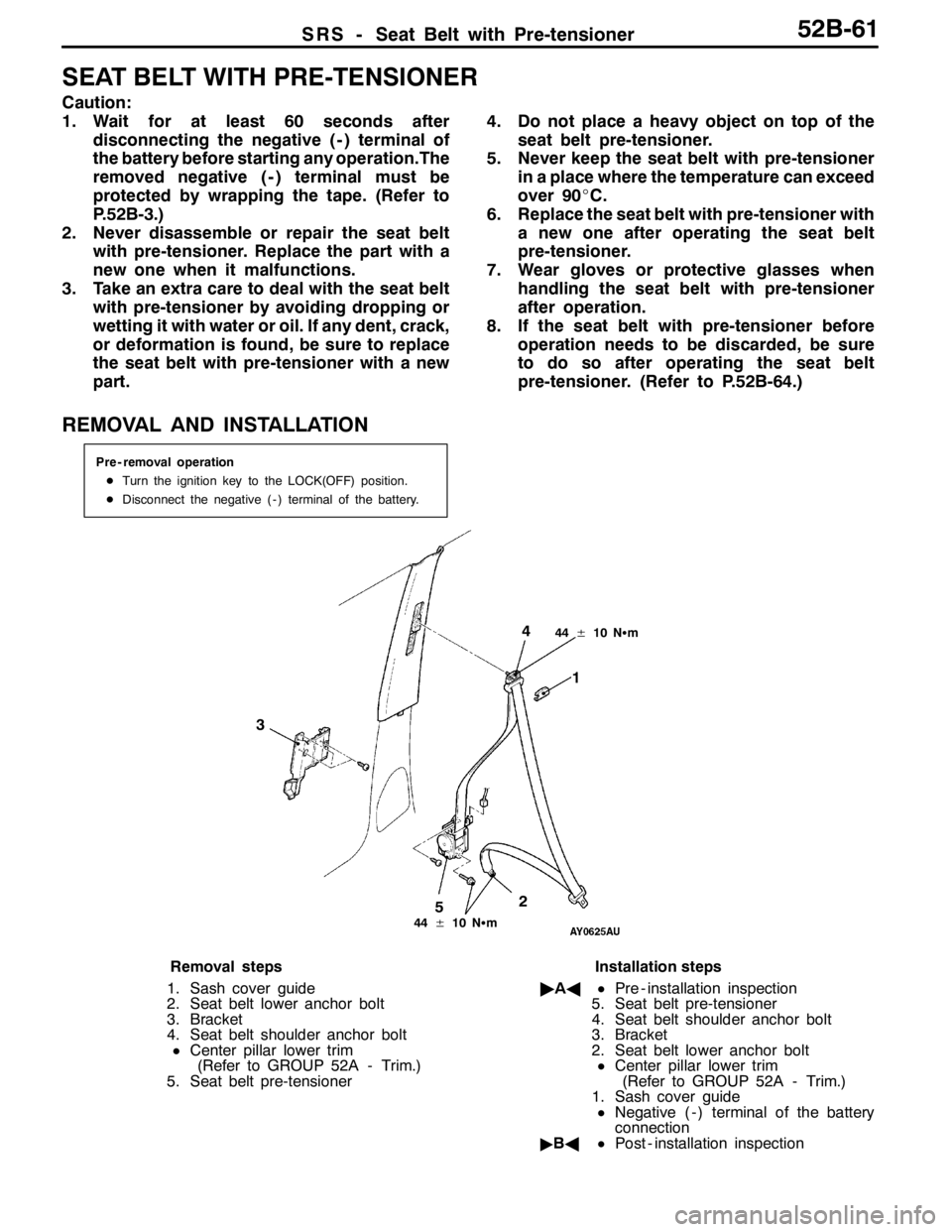
REMOVAL AND INSTALLATION
Pre - removal operation
DTurn the ignition key to the LOCK(OFF) position.
DDisconnect the negative ( - ) terminal of the battery.
1 4
3
2
44±10 NSm
44±10 NSm
5
Removal steps
1. Sash cover guide
2. Seat belt lower anchor bolt
3. Bracket
4. Seat belt shoulder anchor bolt
DCenter pillar lower trim
(Refer to GROUP 52A - Trim.)
5. Seat belt pre-tensionerInstallation steps
"AA
DPre - installation inspection
5. Seat belt pre-tensioner
4. Seat belt shoulder anchor bolt
3. Bracket
2. Seat belt lower anchor bolt
DCenter pillar lower trim
(Refer to GROUP 52A - Trim.)
1. Sash cover guide
DNegative ( - ) terminal of the battery
connection
"BADPost - installation inspection
Page 1404 of 1449
ServiceSpecifications/Lubricants/
Special ToolsHEATER, AIR CONDITIONER AND VENTILATION-55-2
SERVICE SPECIFICATIONS
ItemStandard value
Idlid()NP85050Idlingspeed(rpm):NorPrange850±50Idlingspeed(rpm):NorPrange850±50Idlingspeed(rpm):NorPrange850r50
Idle-up speed (rpm): N or P range850±50
Register resistance (for blower motor)ΩHI - LO (between terminals 1 and 3)2.54g()
HI - ML (between terminals 1 and 6)1.24
HI - MH (between terminals 1 and 4)0.6
Air conditioner compressor air gap mm0.3 – 0.5
Refrigerant temperature switch operating temperature (_C)ContinuitySlightly below 150gppgp()
No continuity150 or higher (until tempera-
ture falls to 120 when OFF)
NOTE* : When disconnected the compressor connector at A/C ON
LUBRICANTS
ItemsSpecified lubricantsQuantity
Compressor oil mLSUN PAG 56130±10
Pipe couplingSUN PAG 56As required
Refrigerant (g)R134a (HFC-134a)550±20
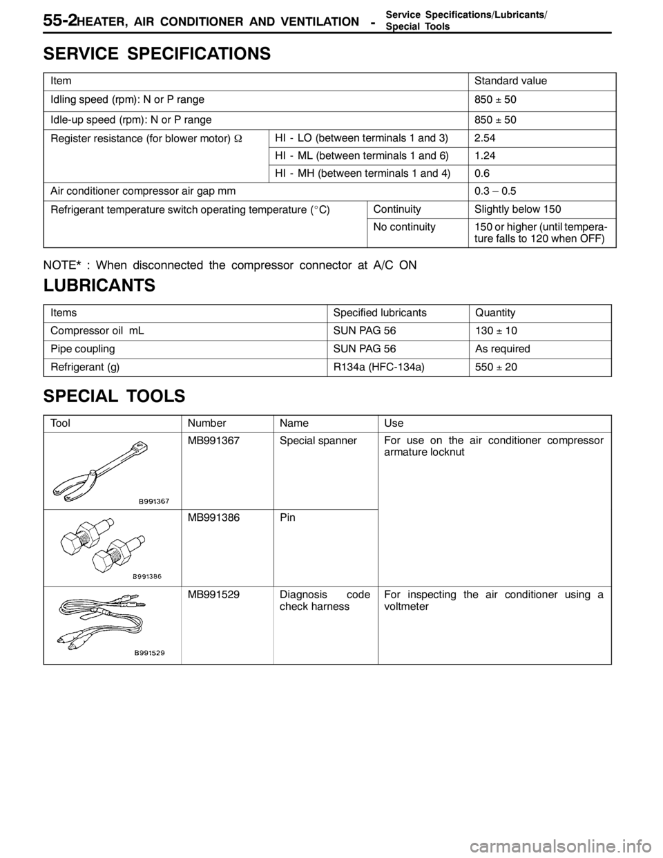
SPECIAL TOOLS
ToolNumberNameUse
MB991367Special spannerFor use on the air conditioner compressor
armature locknut
MB991386Pin
MB991529Diagnosis code
check harnessFor inspecting the air conditioner using a
voltmeter