Page 974 of 1449

REAR AXLE -Knuckle27B-28
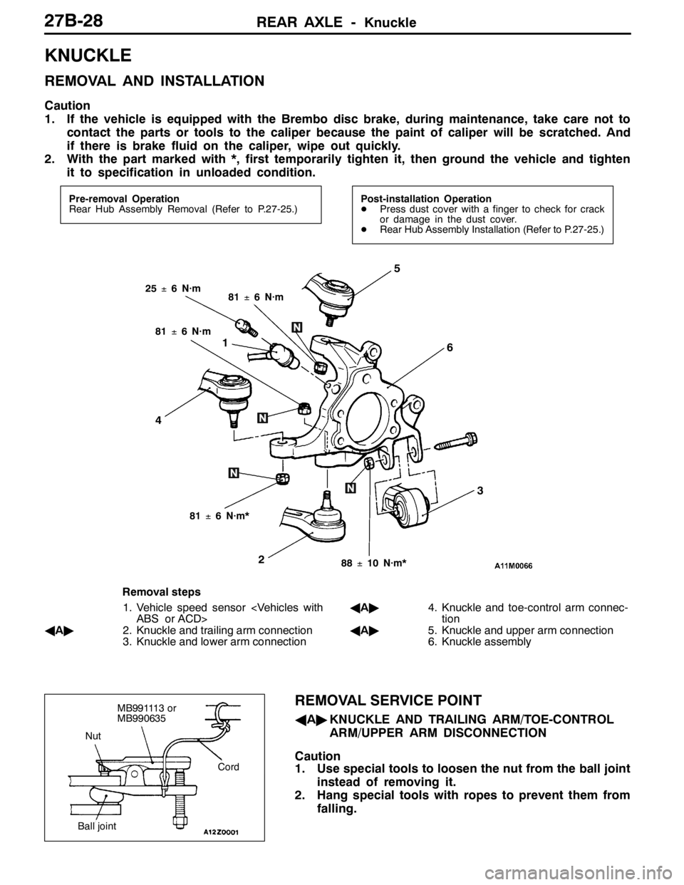
KNUCKLE
REMOVAL AND INSTALLATION
Caution
1. If the vehicle is equipped with the Brembo disc brake, during maintenance, take care not to
contact the parts or tools to the caliper because the paint of caliper will be scratched. And
if there is brake fluid on the caliper, wipe out quickly.
2. With the part marked with *, first temporarily tighten it, then ground the vehicle and tighten
it to specification in unloaded condition.
Pre-removal Operation
Rear Hub Assembly Removal (Refer to P.27-25.)Post-installation Operation
DPress dust cover with a finger to check for crack
or damage in the dust cover.
DRear Hub Assembly Installation (Refer to P.27-25.)
1
2
3
4
5
6
25±6 N·m81±6 N·m
81±6 N·m*
88±10 N·m*
81±6 N·m
Removal steps
1. Vehicle speed sensor
ABS or ACD>
AA"2. Knuckle and trailing arm connection
3. Knuckle and lower arm connectionAA"4. Knuckle and toe-control arm connec-
tion
AA"5. Knuckle and upper arm connection
6. Knuckle assembly
REMOVAL SERVICE POINT
AA"KNUCKLE AND TRAILING ARM/TOE-CONTROL
ARM/UPPER ARM DISCONNECTION
Caution
1. Use special tools to loosen the nut from the ball joint
instead of removing it.
2. Hang special tools with ropes to prevent them from
falling.
Nut
Cord
Ball joint
MB991113 or
MB990635
Page 975 of 1449

REAR AXLE -Drive Shaft27B-29
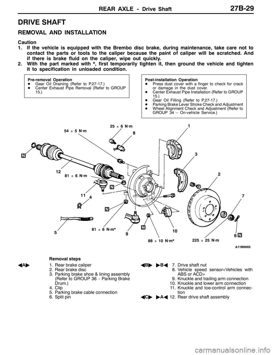
DRIVE SHAFT
REMOVAL AND INSTALLATION
Caution
1. If the vehicle is equipped with the Brembo disc brake, during maintenance, take care not to
contact the parts or tools to the caliper because the paint of caliper will be scratched. And
if there is brake fluid on the caliper, wipe out quickly.
2. With the part marked with *, first temporarily tighten it, then ground the vehicle and tighten
it to specification in unloaded condition.
Pre-removal Operation
DGear Oil Draining (Refer to P.27-17.)
DCenter Exhaust Pipe Removal (Refer to GROUP
15.)Post-installation Operation
DPress dust cover with a finger to check for crack
or damage in the dust cover.
DCenter Exhaust Pipe Installation (Refer to GROUP
15.)
DGear Oil Filling (Refer to P.27-17.)
DParking Brake Lever Stroke Check and Adjustment
DWheel Alignment Check and Adjustment (Refer to
GROUP 34 – On-vehicle Service.)
4
1
3
7
6510
2
8
9
11
12
225±25 N·m
54±5 N·m
88±10 N·m*
81±6 N·m*
81±6 N·m
25±6 N·m
Removal steps
AA"1. Rear brake caliper
2. Rear brake disc
3. Parking brake shoe & lining assembly
(Refer to GROUP 36 - Parking Brake
Drum.)
4. Clip
5. Parking brake cable connection
6. Split pinAB""BA7. Drive shaft nut
8. Vehicle speed sensor
ABS or ACD>
9. Knuckle and trailing arm connection
10. Knuckle and lower arm connection
11. Knuckle and toe-control arm connec-
tion
AC""AA12. Rear drive shaft assembly
Page 1032 of 1449
FRONT SUSPENSION -Strut Assembly33A-6
STRUT ASSEMBLY
REMOVAL AND INSTALLATION
Post-installation Operation
Wheel alignment check and adjustment (Refer to
P.33A-4.)
44±5N·m
3
21
167±9N·m
4
5
Removal steps
1. Front wheel speed sensor harness
bracket
2. Brake hose bracket3. Knuckle connection
4. Strut mounting nut
5. Strut assembly
Page 1044 of 1449
35A-2
BASIC BRAKE
SYSTEM
CONTENTS
GENERAL INFORMATION 3..................
SERVICE SPECIFICATIONS 5.................
LUBRICANTS 6..............................
SEALANT 6..................................
SPECIAL TOOLS 6...........................
ON-VEHICLE SERVICE 7.....................
Brake Pedal Check and Adjustment 7............
Brake Booster Operating Test 8.................
Check Valve Operation Check 9.................
Proportioning Valve Function Test
9......................Bleeding 10....................................
Brake Fluid Level Sensor Check 11.............
Disc Brake Pad Check and Replacement 11......
Disc Brake Rotor Check 13.....................
Brake Disc Thickness Check 14.................
Brake Disc Run-out Check and Correction 14....
BRAKE PEDAL 16...........................
PROPORTIONING VALVE, MASTER
CYLINDER AND BRAKE BOOSTER 17........
Master Cylinder 19.............................
DISC BRAKE 20.............................
Page 1053 of 1449

BASIC BRAKE SYSTEM -On-vehicle Service35A-11
BRAKE FLUID LEVEL SENSOR CHECK
The brake fluid level sensor is in good condition if there is
no continuity when the float surface is above “MIN” and if
there is continuity when the float surface is below “MIN”.
DISC BRAKE PAD CHECK AND REPLACEMENT
NOTE
The wear indicator contacts the brake disc when the brake
pad thickness reaches approximately 2 mm and emit a
squealing sound to warn the driver.
1. Check the brake pad thickness through the caliper body
check port.
Standard value: 10.0 mm
Limit: 2.0 mm
2. When the thickness is less than the limit, always replace
the pads at an axle set.
3. Remove the pin bolt. Pivot the caliper assembly and hold
it with wires.
Caution
Do not wipe off the special grease that is on the pin
or allow it to contaminate the pin.
4. Remove the following parts from the caliper support.
1. Pad and wear indicator assembly
2. Pad assembly
3. Clip
4. Outer shim
5. In order to measure the brake drag force after pad
installation, measure the rotary-sliding resistance of the
hub with the pads removed. (Refer to P.35A-21.)
6. Install the pads and caliper assembly, and then check
the brake drag force. (Refer to P.35A-21.)
14Z0017
Front Rear
Front Rear
Front Rear
12 34
3
1
2 3
4
3
Page 1060 of 1449

BASIC BRAKE SYSTEM -ProportioningValve,MasterCylinder
and Brake Booster35A-18
Master cylinder removal steps
1. Clutch hose connection
2. Brake fluid level sensor connector
3. Reservoir cap assembly
4. Brake fluid level sensor
5. Brake pipe connection
6. Proportioning valve
7. O ring
8. Master cylinder
Proportioning valve removal steps
5. Brake pipe connection
6. Proportioning valve
7. O ring
Brake booster removal steps
1. Clutch hose connection
2. Brake fluid level sensor connector5. Brake pipe connection
8. Master cylinder
"BADPush rod protrusion amount check and
adjustment
"AA9. Vacuum hose
(With built-in check valve)
10. Snap pin
11. Pin assembly
12. Clevis
DRemove A/C liquid pipe B
from the
retaining clip.(Refer to GROUP 55A
- Refrigerant Line.)
13. Brake booster
14. Sealer
Fitting removal steps
"AA9. Vacuum hose
(With built-in check valve)
15. Fitting
INSTALLATION SERVICE POINTS
"AAVACUUM HOSE CONNECTION
Insert the vacuum hose to the brake booster with its paint
mark facing upward, and then secure the hose by using the
hose clip.
"BAPUSH ROD PROTRUSION AMOUNT CHECK AND
ADJUSTMENT
1. Measure dimension (A).
Standard value (A) : 8.98 - 9.23 mm
NOTE
When a negative pressure of 66.7 kPa is applied to the
brake booster, the push rod should protrude 10.27 – 10.53
mm.
Block gauge Measuring distance A
A
Page 1071 of 1449

35B-1
ANTI-SKID
BRAKING SYSTEM
(ABS) <4WD>
CONTENTS
GENERAL INFORMATION 2..................
SERVICE SPECIFICATIONS 3.................
LUBRICANTS Refer to GROUP 35A..........
SEALANT Refer to GROUP 35A..............
SPECIAL TOOLS 4...........................
TROUBLESHOOTING 4.......................
ON-VEHICLE SERVICE 26....................
Brake Pedal Check and Adjustment
Refer to GROUP 35A ..........................
Brake Booster Operating Test
Refer to GROUP 35A ..........................
Check Valve Operation Check
Refer to GROUP 35A ..........................
Bleeding Refer to GROUP 35A..................
Brake Fluid Level Sensor Check
Refer to GROUP 35A ..........................
Disc Brake Pad Check and
Replacement Refer to GROUP 35A..............Disc Brake Rotor Check Refer to GROUP 35A...
Brake Disc Thickness Check
Refer to GROUP 35A ..........................
Brake Disc Run-out Check and Correction
Refer to GROUP 35A ..........................
Wheel Speed Sensor Output Voltage Check
26 ............................................
Hydraulic Unit Check 28........................
Remedy for a Flat Battery 29...................
BRAKE PEDAL Refer to GROUP 35A........
MASTER CYLINDER AND BRAKE
BOOSTER Refer to GROUP 35A............
DISC BRAKE Refer to GROUP 35A..........
HYDRAULIC UNIT AND ABS-ECU 30.........
WHEEL SPEED SENSOR 33..................
G SENSORS AND STEERING WHEEL
SENSOR 35..................................
Page 1072 of 1449

ABS <4WD> -General Information35B-2
GENERAL INFORMATION
ABS has been adopted as optional equipment in
RS-IIto maintain directional stability and steering
performance during sudden braking or braking on
slippery road surfaces.
The ABS control method is a 4-sensor, 4-channel
method which provides independent control for all
wheels.
Following system for Lancer EVOLUTION-VII has
been modified from Lancer EVOLUTION-VI Tommi
Makinen Edition.DBy adding lateral G sensor, longitudinal G
sensor and steering wheel sensor, optimized
ABS control at the time of cornering.
DBy inputting parking brake switch signal to
ABS-ECU with pulling parking brake lever, ABS
control has been optimized.
DABS-ECU outputs ABS signal to 4WD-ECU.
DG sensor (lateral), steering wheel sensor and
parking brake switch have been added to the
diagnosis and service data.
DABS-ECU connector has been changed.
EBD CONTROL
In ABS, electronic control method is used by which
the rear wheel brake hydraulic pressure during
braking is regulated by rear wheel control solenoid
valves in accordance with the vehicle’s rate of
deceleration and the front and rear wheel slippage
which are calculated from the each wheel speed
sensor’s signal. EBD control is a control system
which provides a high level of control for both vehicle
braking force and vehicle stability. The system has
the following features:
DBecause the system provides the optimum rear
wheel braking force regardless of the vehicleladen condition and the condition of the road
surface, the system reduces the required pedal
depression force, particularly when the vehicle
is heavily laden or driving on road surfaces
with high frictional coefficients.
DBecause the duty placed on the front brakes
has been reduced, the increases in pad
temperature can be controlled to improve the
wear resistance characteristics of the pad,
during front brakes applying.
DControl valves such as the proportioning valve
are no longer required.
SPECIFICATIONS
ItemSpecifications
ABS control method4-sensor, 4-channel
No. of ABS rotor teethFront43
Rear43
ABS speed sensorTypeMagnet coil typep
Gap between sensor and rotor mm0.85 / 0.60 (non-adjustable type)