Page 419 of 1449

ENGINE -On-vehicle Service11A-13
(2) If there is a problem with the lash adjusters, the noise
will almost never disappear, even if the engine has
been run at idle to let it warm up.
The only case where the noise might disappear is
if the oil in the engine has not been looked after
properly and oil sludge has caused the lash adjusters
to stick.
1. Start the engine.
2. Check that the noise occurs immediately after the engine
is started, and that the noise changes in accordance
with changes in the engine speed.
If the noise does not occur immediately after the engine
is started, or if it does not change in accordance with
the engine speed, the problem is not being caused by
the lash adjusters, so check for some other cause of
the problem. Moreover, if the noise does not change in
accordance with the engine speed, the cause of the
problem is probably not with the engine. (In these cases,
the lash adjusters are normal.)
3. While the engine is idling, check that the noise level does
not change when the engine load is varied.
If the noise level changes, the cause of the noise is
probably parts striking because of worn crankshaft
bearings or connecting rod bearings. (In such cases, the
lash adjusters are normal.)
4. After the engine has warmed up, run it at idle and check
if any noise can be heard.
If the noise has become smaller or disappeared, oil sludge
could make the lash adjusters stick. Clean the lash
adjusters. (Refer to the Engine Workshop Manual.) If not
improved, go to step 5.
5. Bleed air from the lash adjusters.
6. If the noise has not disappeared even after the air
bleeding, clean the lash adjusters.
(Refer to GROUP 11B - Rocker Arms and Camshaft.)
NOTE
(1) If the vehicle is parked on a slope for a long period
of time, the amount of oil inside the lash adjuster
will decrease, and air may get into the high pressure
chamber when starting the engine.
(2) After parking the vehicle for long periods, the oil drains
out of the oil passage, and it takes time for the oil
to be supplied to the lash adjuster, so air can get
into the high pressure chamber.
(3) If either of the above situations occur, the abnormal
noise can be eliminated by bleeding the air from inside
the lash adjusters.
Page 420 of 1449

ENGINE -On-vehicle Service11A-14
1. Check the engine oil and replenish or replace the oil
if necessary.
NOTE
(1) If there is a only small amount of oil, air will be drawn
in through the oil screen and will get into the oil
passage.
(2) If the amount of oil is greater than normal, then the
oil will being mixed by the crankshaft and a large
amount of air may get mixed into the oil.
(3) If the oil is degenerated, air and oil will not separate
easily in oil, and the amount of air mixed into the
oil will increase.
(4) If the air which has been mixed in with the oil due
to any of the above reasons gets into the high pressure
chamber of the lash adjuster, the air inside the high
pressure chamber will be compressed when the valve
is open and the lash adjuster will over-compress,
resulting in abnormal noise when the valve closes.
This is the same effect as if the valve clearance is
adjusted to be too large by mistake. If the air inside
the lash adjusters is then released, the operation
of the lash adjusters will return to normal.
2. Run the engine at idle for 1 - 3 minutes to let it warm
up.
3. With no load on the engine, repeat the drive pattern shown
in the illustration at left and check if the abnormal noise
disappears. (The noise should normally disappear after
10 - 30 repetitions, but if there is no change in the noise
level after 30 repetitions or more, the problem is probably
not due to air inside the lash adjusters.)
4. After the noise has disappeared, repeat the drive pattern
shown in the illustration at left a further 5 times.
5. Run the engine at idle for 1 - 3 minutes and check that
the noise has disappeared.
Good
High-pressure chamber
Gradually open the
throttle valve.
Drive pattern for air bleeding
Close the throttle
valve.
Approx.
3,000 r/min
15
seconds15
seconds
Idle speed
Once
Page 427 of 1449

ENGINE -Camshaft and Camshaft Oil Seal11A-21
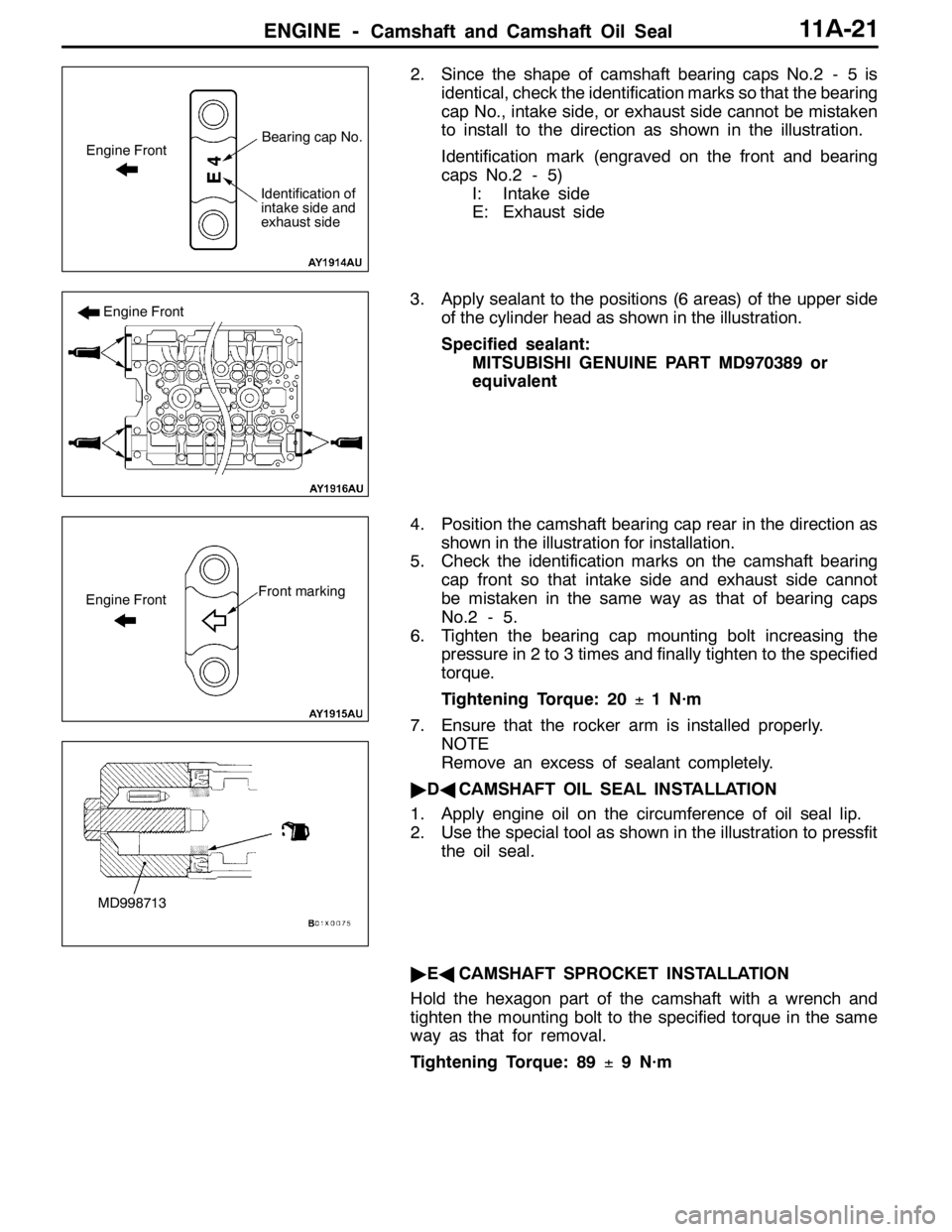
2. Since the shape of camshaft bearing caps No.2 - 5 is
identical, check the identification marks so that the bearing
cap No., intake side, or exhaust side cannot be mistaken
to install to the direction as shown in the illustration.
Identification mark (engraved on the front and bearing
caps No.2 - 5)
I: Intake side
E: Exhaust side
3. Apply sealant to the positions (6 areas) of the upper side
of the cylinder head as shown in the illustration.
Specified sealant:
MITSUBISHI GENUINE PART MD970389 or
equivalent
4. Position the camshaft bearing cap rear in the direction as
shown in the illustration for installation.
5. Check the identification marks on the camshaft bearing
cap front so that intake side and exhaust side cannot
be mistaken in the same way as that of bearing caps
No.2 - 5.
6. Tighten the bearing cap mounting bolt increasing the
pressure in 2 to 3 times and finally tighten to the specified
torque.
Tightening Torque: 20±1 N·m
7. Ensure that the rocker arm is installed properly.
NOTE
Remove an excess of sealant completely.
"DACAMSHAFT OIL SEAL INSTALLATION
1. Apply engine oil on the circumference of oil seal lip.
2. Use the special tool as shown in the illustration to pressfit
the oil seal.
"EACAMSHAFT SPROCKET INSTALLATION
Hold the hexagon part of the camshaft with a wrench and
tighten the mounting bolt to the specified torque in the same
way as that for removal.
Tightening Torque: 89±9 N·m
Engine FrontBearing cap No.
Identification of
intake side and
exhaust side
Engine Front
Front markingEngine Front
MD998713
Page 435 of 1449
ENGINE -Cylinder Head Gasket11A-29
5.0±1.0 N·m
61
2
3 4
57
8
910
11 12
1314
13±1 N·m
15
16
17
5.0±1.0 N·m
1819
9.0±1.0 N·m
9.0±1.0 N·m
(Engine oil)
1
Removal steps
1. Ignition coil connector
2. Crank angle sensor connector
3. Oxygen sensor connector
4. Fuel pressure solenoid valve
connector
5. Detonation sensor connector
6. Purge control solenoid valve
connector
7. Throttle position sensor connector
8. Idle speed control servo connector
9. Injector connector
10. Camshaft position sensor connector
11. Engine coolant temperature gauge
unit connector12. Engine coolant temperature sensor
connector
DRocker cover (Refer to P.11A-17.)
13. EGR solenoid valve connector
14. Secondary air control solenoid valve
connector
15. Vacuum tank, solenoid valve, vacuum
pipe and hose assembly
16. Brake booster vacuum hose
connection
17. Oil level gauge and guide assembly
18. O-ring
19. Purge hose connection
Page 436 of 1449
ENGINE -Cylinder Head Gasket11A-30
23 31
24 26 27 28
2930
22
22±4 N·m5.0±1.0 N·m
31±3 N·m
(Engine oil)
2021
25
9.0±1.0 N·m
14±1 N·m
33 32
(Engine oil)
78±2 N·m to 0 N·m to 20±2 N·m
to +90_to +90_(cold start)
35±6 N·m44±5 N·m
34
20. Alternator brace connection
21. Intake manifold stay
22. Oil return pipe gasket
23. Oil return pipe
24. Oil return pipe gasket
"DA25. Oil return pipe gasket
26. Exhaust fitting bracket
DWater outlet fitting and thermostat
case assembly (Refer to Group 15
- Water Hose and Pipe.)27. Water hose connection
28. Heater hose connection
29. Fuel return hose connection
"CA30. Fuel high pressure hose connection
"CA31. O-ring
AA""BA32. Cylinder head bolt
33. Cylinder head assembly
"AA34. Cylinder head gasket
Page 438 of 1449

ENGINE -Cylinder Head Gasket11A-32
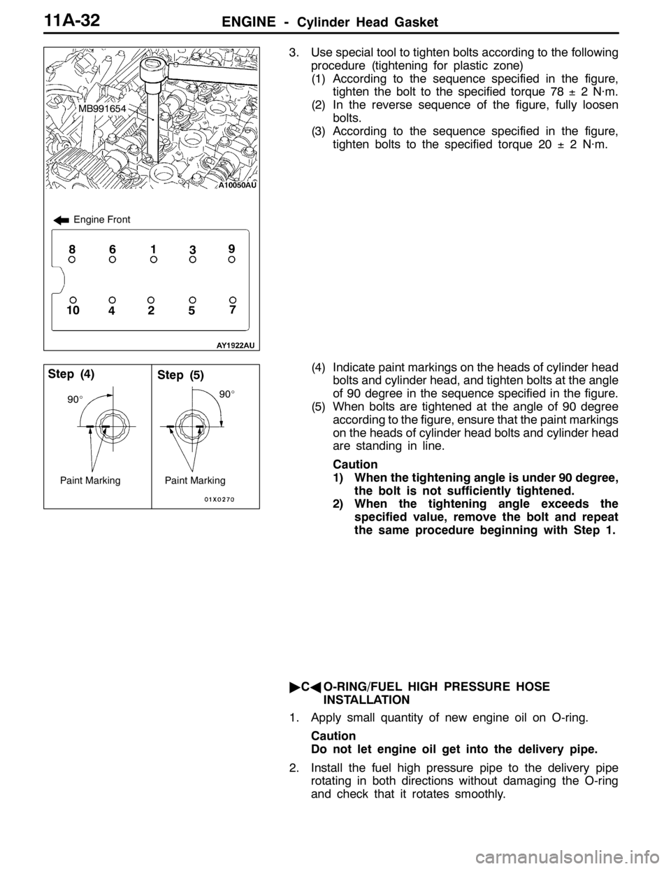
3. Use special tool to tighten bolts according to the following
procedure (tightening for plastic zone)
(1) According to the sequence specified in the figure,
tighten the bolt to the specified torque 78±2 N·m.
(2) In the reverse sequence of the figure, fully loosen
bolts.
(3) According to the sequence specified in the figure,
tighten bolts to the specified torque 20±2 N·m.
(4) Indicate paint markings on the heads of cylinder head
bolts and cylinder head, and tighten bolts at the angle
of 90 degree in the sequence specified in the figure.
(5) When bolts are tightened at the angle of 90 degree
according to the figure, ensure that the paint markings
on the heads of cylinder head bolts and cylinder head
are standing in line.
Caution
1) When the tightening angle is under 90 degree,
the bolt is not sufficiently tightened.
2) When the tightening angle exceeds the
specified value, remove the bolt and repeat
the same procedure beginning with Step 1.
"CAO-RING/FUEL HIGH PRESSURE HOSE
INSTALLATION
1. Apply small quantity of new engine oil on O-ring.
Caution
Do not let engine oil get into the delivery pipe.
2. Install the fuel high pressure pipe to the delivery pipe
rotating in both directions without damaging the O-ring
and check that it rotates smoothly.
1
5427
3869
10
Engine Front
MB991654
Step (4)Step (5)
Paint Marking
90_
Paint Marking
90_
Page 439 of 1449
ENGINE -Cylinder Head Gasket11A-33
3. In case of not rotating smoothly, remove the fuel high
pressure hose and insert it to the delivery pipe again
after checking damage of the O-ring since there is a
possibility of O-ring engagement.
4. Tighten fuel high pressure hose mounting bolts to the
specified torque.
Tightening Torque: 5.0±1.0 N·m
"DAOIL RETURN PIPE GASKET INSTALLATION
Gasket should be replaced with a new one, and set the convex
part to the position as shown in the illustration for installation.
NOTE
There is no specific direction indicated for installing the
turbocharger side of the oil return pipe gasket.
Convex part
Page 450 of 1449
ENGINE -Engine Assembly11A-44
1
2
3 4
5
67
8
910
11 12
13
14
26±5 N·m
14±3 N·m
1516
18
5.0±1.0 N·m
1
5.0±1.0 N·m
11±1 N·m
17
Removal steps
1. Ignition coil connector
2. Crank angle sensor connector
3. Oxygen sensor connector
4. Fuel pressure solenoid valve
connector
5. Detonation sensor connector
6. Purge control solenoid valve
connector
7. Throttle position sensor connector
8. Idle speed control servo connector
9. Injector connector
10. Camshaft position sensor connector11. Engine coolant temperature gauge
unit connector
12. Engine coolant temperature sensor
connector
13. Alternator connector
14. EGR solenoid valve connector
15. Secondary air control solenoid valve
connector
16. Engine oil pressure switch
connector
17. Waste gate actuator mounting bolt
AA"18. Drive belt