Page 780 of 1449

ENGINE AND EMISSION CONTROL -Emission Control System
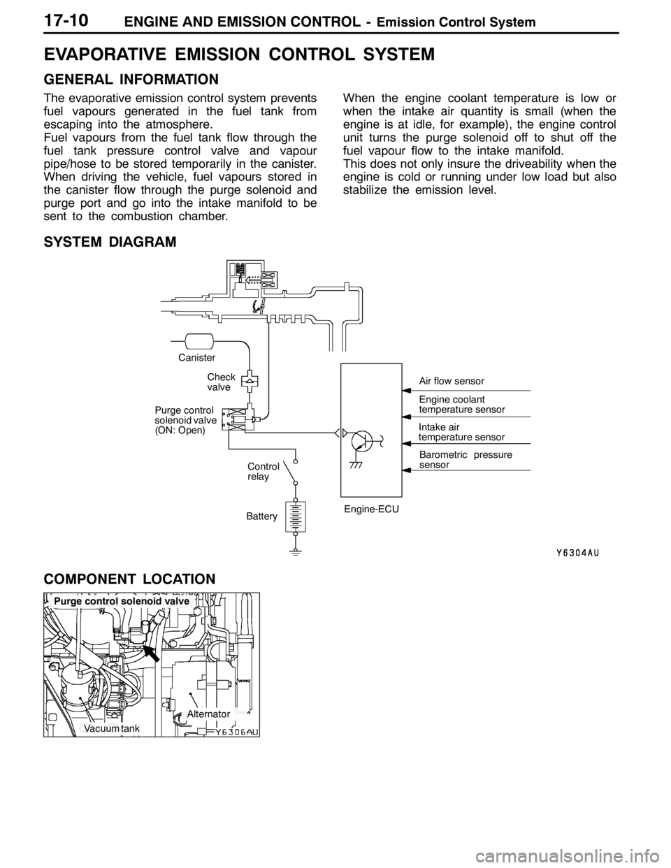
Vacuum tank
Alternator
Purge control solenoid valve
17-10
EVAPORATIVE EMISSION CONTROL SYSTEM
GENERAL INFORMATION
The evaporative emission control system prevents
fuel vapours generated in the fuel tank from
escaping into the atmosphere.
Fuel vapours from the fuel tank flow through the
fuel tank pressure control valve and vapour
pipe/hose to be stored temporarily in the canister.
When driving the vehicle, fuel vapours stored in
the canister flow through the purge solenoid and
purge port and go into the intake manifold to be
sent to the combustion chamber.When the engine coolant temperature is low or
when the intake air quantity is small (when the
engine is at idle, for example), the engine control
unit turns the purge solenoid off to shut off the
fuel vapour flow to the intake manifold.
This does not only insure the driveability when the
engine is cold or running under low load but also
stabilize the emission level.
SYSTEM DIAGRAM
BatteryIntake air
temperature sensor
Barometric pressure
sensor
Check
valve
Canister
Control
relay
Purge control
solenoid valve
(ON: Open)
Engine-ECUEngine coolant
temperature sensor Air flow sensor
COMPONENT LOCATION
Page 783 of 1449

ENGINE AND EMISSION CONTROL -Emission Control System17-13
EXHAUST GAS RECIRCULATION (EGR) SYSTEM
GENERAL INFORMATION
The exhaust gas recirculation (EGR) system lowers
the nitrogen oxide (NOx) emission level. When the
air/fuel mixture combustion temperature is high,
a large quantity of nitrogen oxides (NOx) is
generated in the combustion chamber. Therefore,
this system recirculates part of emission gas fromthe exhaust port of the cylinder head to the
combustion chamber through the intake manifold
to decrease the air/fuel mixture combustion
temperature, resulting in reduction of NOx.
The EGR flow rate is controlled by the EGR valve
so as not to decrease the driveability.
OPERATION
The EGR valve is being closed and does not
recirculate exhaust gases under one of the following
conditions. Otherwise, the EGR valve is opened
and recirculates exhaust gases.DThe engine coolant temperature is low.
DThe engine is at idle.
DThe throttle valve is widely opened.
SYSTEM DIAGRAM
ON Throttle body
EGR control
solenoid valve
Engine
control
relay
Battery EGR valve
Crank angle sensor
Throttle position sensor Engine-ECU
Engine coolant
temperature sensor Air flow sensor
Page 788 of 1449
ENGINE AND EMISSION CONTROL -Emission Control System17-18
CANISTER
REMOVAL AND INSTALLATION
Pre-removal and Post-installation Operation
DAir Pipe C, Air Hose D Removal and Installation (Refer to GROUP 15 - Inter Cooler.)
DBattery and Battery Tray Removal and Installation
DAir Cleaner Assembly Removal and Installation (Refer to GROUP 15 - Air Cleaner.)
1 2
3 4
5
67
89
Canister removal steps
1. Purge hose
2. Check valve
3. Vapor hose
4. Vent connector
5. Vapor hose6. Hose clamp
7. Canister
8. Fuel high pressure hose
9. Canister bracket assembly
Page 789 of 1449
ENGINE AND EMISSION CONTROL -Emission Control System17-19
CATALYTIC CONVERTER
GENERAL INFORMATION
The three-way catalytic converter, together with
the closed loop air-fuel ratio control based on the
oxygen sensor signal, oxidizes carbon monoxides
(CO) and hydrocarbons (HC) and reduces nitrogen
oxides (NOx).When the mixture is controlled at stoichiometric
air-fuel ratio, the three-way catalytic converter
provides the highest purification against the three
constituents, namely, CO, HC and NOx.
REMOVAL AND INSTALLATION
Pre-removal and Post-installation Operation
DUnder Cover Removal and Installation (Refer to GROUP 51 - Front Bumper.)
DCrossmember Bar Removal and Installation (Refer to GROUP 32 - Engine Roll Stopper, Centermember.)
123
49±10N·m
13±2N·m 13±2N·m
59±10N·m
50±5N·m
Removal steps
1. Spring
2. Front exhaust pipe
3. Catalytic converter
Page 1149 of 1449

42-1
BODY
CONTENTS
HOOD2 .................................
ON-VEHICLE SERVICE 2..................
Adjustment of Clearance around Hood 2......
Adjustment of Alignment of Hood Stepped
Portion and Hood Striker 2..................
Adjustment of Hood Height 2.................
HOOD 3..................................
FENDER4 ..............................
SPECIAL TOOL 4.........................
FENDER 5................................
FUEL FILLER DOOR7 .................
STRUT TOWER BAR AND REAR END
CROSS BAR8 ...........................
WINDOW GLASS9 .....................
ADHESIVE 9..............................
SPECIAL TOOLS 9........................
WINDOW REPAIR 9.......................
WINDSHIELD 11...........................
REAR WINDOW GLASS 16................
DOORS19 ..............................
SERVICE SPECIFICATIONS 19.............ADHESIVES 19............................
SPECIAL TOOLS 19.......................
TROUBLESHOOTING 20...................
ON-VEHICLE SERVICE 20.................
Door Adjustment 20.........................
Door Window Glass Adjustment 21...........
Adjustment and Replacement during Power
Window Malfunction 22......................
Power Window Safety Mechanism Check 22..
Power Window Timer Function Check 22......
Door Outside Handle Looseness Check 23....
Power Window Operation Current Check 23...
Circuit Breaker Check 23....................
Power Window Check 23....................
Door Inside Handle Looseness Check and
Adjustment 24...............................
DOOR ASSEMBLY 25......................
DOOR TRIM AND
WATERPROOF FILM 27....................
DOOR GLASS AND REGULATOR 32.......
DOOR HANDLE AND LATCH 35...........
WINDOW GLASS RUNCHANNEL AND
DOOR OPENING WEATHERSTRIP 38.......
TRUNK LID41 ..........................
Page 1155 of 1449
BODY -Fuel Filler Door42-7
FUEL FILLER DOOR
REMOVAL AND INSTALLATION
Pre-removal and Post-installation Operations
DRear Seat Removal and Installation. (Refer to GROUP
52A.)
DFront Scuff Plate (Driver’s Side), Rear Scuff Plate(Driver’s Side), Center Pillar Lower Trim (Driver’s
Side), Quarter Trim (Driver’s Side) Removal and
Installation (Refer to GROUP 52A – Trim.)
5
1
3 4 3
2
5.0±1.0 N·m
Adjustment of clearance around
fuel filler door
Removal steps
1. Fuel filler door panel assembly
2. Clip
3. Fuel filler door hook assembly4. Fuel filler door lock release cable
5. Fuel filler door lock release handle
Page 1322 of 1449

54A-2
CHASSIS
ELECTRICAL
CONTENTS
BATTERY 4..............................
SERVICE SPECIFICATION 4....................
ON-VEHICLE SERVICE 4......................
Fluid Level and Specific Gravity Check 4........
Charging 4.................................
Battery Testing Procedure 5...................
IGNITION SWITCH AND IMMOBILIZER
SYSTEM 6...............................
SPECIAL TOOLS 6............................
TROUBLESHOOTING 6........................
IMMOBILIZER-ECU CHECK 10.................
IGNITION SWITCH 11..........................
COMBINATION METER 14................
SERVICE SPECIFICATIONS 14.................
SEALANT 14..................................
SPECIAL TOOLS 15...........................
TROUBLESHOOTING 15.......................
ON-VEHICLE SERVICE 19.....................Speedometer Check 19......................
Tachometer Check 20........................
Fuel Gauge Unit Check 20....................
Engine Coolant Temperature Gauge
Unit Check 21...............................
COMBINATION METER 22.....................
HEADLAMP ASSEMBLY 24...............
SERVICE SPECIFICATIONS 24.................
TROUBLESHOOTING 24.......................
ON-VEHICLE SERVICE 24.....................
Headlamp Aiming 24.........................
Headlamp Intensity Measurement 28...........
Headlamp Bulb(low beam)Replacement28 ....
Headlamp Bulb(high beam)Replacement29 ...
Position Lamp Bulb Replacement29 ...........
Front Turn Signal Lamp Bulb Replacement29 ...
Headlamp Auto Cut Adjustment Procedure29 ...
HeadlampAuto Cut Function Check 29.........
HEADLAMP ASSEMBLY 30....................
CONTINUED ON NEXT PAGE
Page 1329 of 1449

CHASSIS ELECTRICAL -Ignition Switch and Immobilizer System54A-9
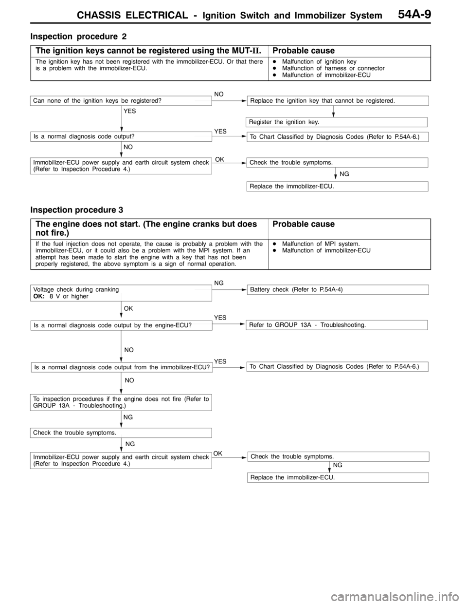
Inspection procedure 2
The ignition keys cannot be registered using the MUT-II.
Probable cause
The ignition key has not been registered with the immobilizer-ECU. Or that there
is a problem with the immobilizer-ECU.DMalfunction of ignition key
DMalfunction of harness or connector
DMalfunction of immobilizer-ECU
Register the ignition key.
YES
NO YESIs a normal diagnosis code output?
NOCan none of the ignition keys be registered?Replace the ignition key that cannot be registered.
To Chart Classified by Diagnosis Codes (Refer to P.54A-6.)
OKImmobilizer-ECU power supply and earth circuit system check
(Refer to Inspection Procedure 4.)
NG
Replace the immobilizer-ECU.
Check the trouble symptoms.
Inspection procedure 3
The engine does not start. (The engine cranks but does
not fire.)
Probable cause
If the fuel injection does not operate, the cause is probably a problem with the
immobilizer-ECU, or it could also be a problem with the MPI system. If an
attempt has been made to start the engine with a key that has not been
properly registered, the above symptom is a sign of normal operation.DMalfunction of MPI system.
DMalfunction of immobilizer-ECU
NGBattery check (Refer to P.54A-4)
YES
NO
Refer to GROUP 13A - Troubleshooting.YES
NO
To Chart Classified by Diagnosis Codes (Refer to P.54A-6.)Is a normal diagnosis code output from the immobilizer-ECU?
OK
Voltage check during cranking
OK:8 V or higher
Is a normal diagnosis code output by the engine-ECU?
NG
OKImmobilizer-ECU power supply and earth circuit system check
(Refer to Inspection Procedure 4.)
NG
Replace the immobilizer-ECU.
Check the trouble symptoms.
Check the trouble symptoms.
NG
To inspection procedures if the engine does not fire (Refer to
GROUP 13A - Troubleshooting.)