2007 MITSUBISHI LANCER EVOLUTION belt
[x] Cancel search: beltPage 1284 of 1449

SRS -Troubleshooting52B-40
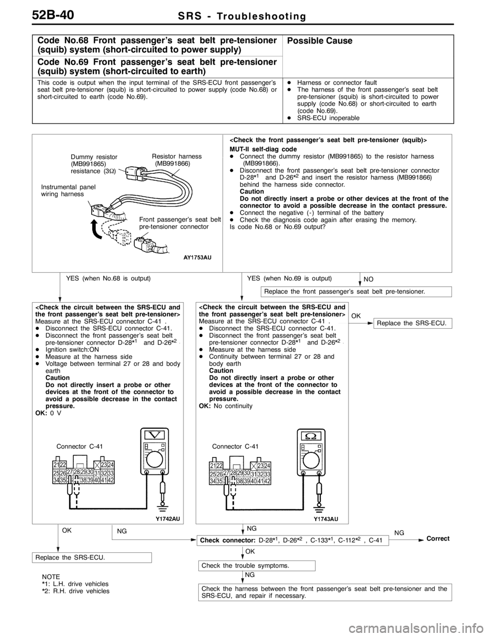
Code No.68 Front passenger’s seat belt pre-tensioner
(squib) system (short-circuited to power supply)Possible Cause
Code No.69 Front passenger’s seat belt pre-tensioner
(squib) system (short-circuited to earth)
This code is output when the input terminal of the SRS-ECU front passenger’s
seat belt pre-tensioner (squib) is short-circuited to power supply (code No.68) or
short-circuited to earth (code No.69).DHarness or connector fault
DThe harness of the front passenger’s seat belt
pre-tensioner (squib) is short-circuited to power
supply (code No.68) or short-circuited to earth
(code No.69).
DSRS-ECU inoperable
NO
Replace the front passenger’s seat belt pre-tensioner.
MUT-II self-diag code
DConnect the dummy resistor (MB991865) to the resistor harness
(MB991866).
DDisconnect the front passenger’s seat belt pre-tensioner connector
D-28*
1and D-26*2and insert the resistor harness (MB991866)
behind the harness side connector.
Caution
Do not directly insert a probe or other devices at the front of the
connector to avoid a possible decrease in the contact pressure.
DConnect the negative ( - ) terminal of the battery
DCheck the diagnosis code again after erasing the memory.
Is code No.68 or No.69 output?
YES (when No.69 is output)YES (when No.68 is output)
Replace the SRS-ECU.
Measure at the SRS-ECU connector C-41 .
DDisconnect the SRS-ECU connector C-41.
DDisconnect the front passenger’s seat belt
pre-tensioner connector D-28*
1and D-26*2.
DIgnition switch:ON
DMeasure at the harness side
DVoltage between terminal 27 or 28 and body
earth
Caution
Do not directly insert a probe or other
devices at the front of the connector to
avoid a possible decrease in the contact
pressure.
OK:0V
NG
Replace the SRS-ECU.
Correct
Check connector:D-28*1, D-26*2, C-133*1, C-112*2, C-41
Check the trouble symptoms.
Check the harness between the front passenger’s seat belt pre-tensioner and the
SRS-ECU, and repair if necessary.OK
Measure at the SRS-ECU connector C-41 .
DDisconnect the SRS-ECU connector C-41.
DDisconnect the front passenger’s seat belt
pre-tensioner connector D-28*
1and D-26*2.
DMeasure at the harness side
DContinuity between terminal 27 or 28 and
body earth
Caution
Do not directly insert a probe or other
devices at the front of the connector to
avoid a possible decrease in the contact
pressure.
OK:No continuity
NG
OK
NG
OK
NG
Resistor harness
(MB991866) Dummy resistor
(MB991865)
resistance (3Ω)
Instrumental panel
wiring harness
Front passenger’s seat belt
pre-tensioner connector
Connector C-41 Connector C-41
NOTE
*1: L.H. drive vehicles
*2: R.H. drive vehicles
Page 1287 of 1449

SRS - SRS Maintenance52B-43
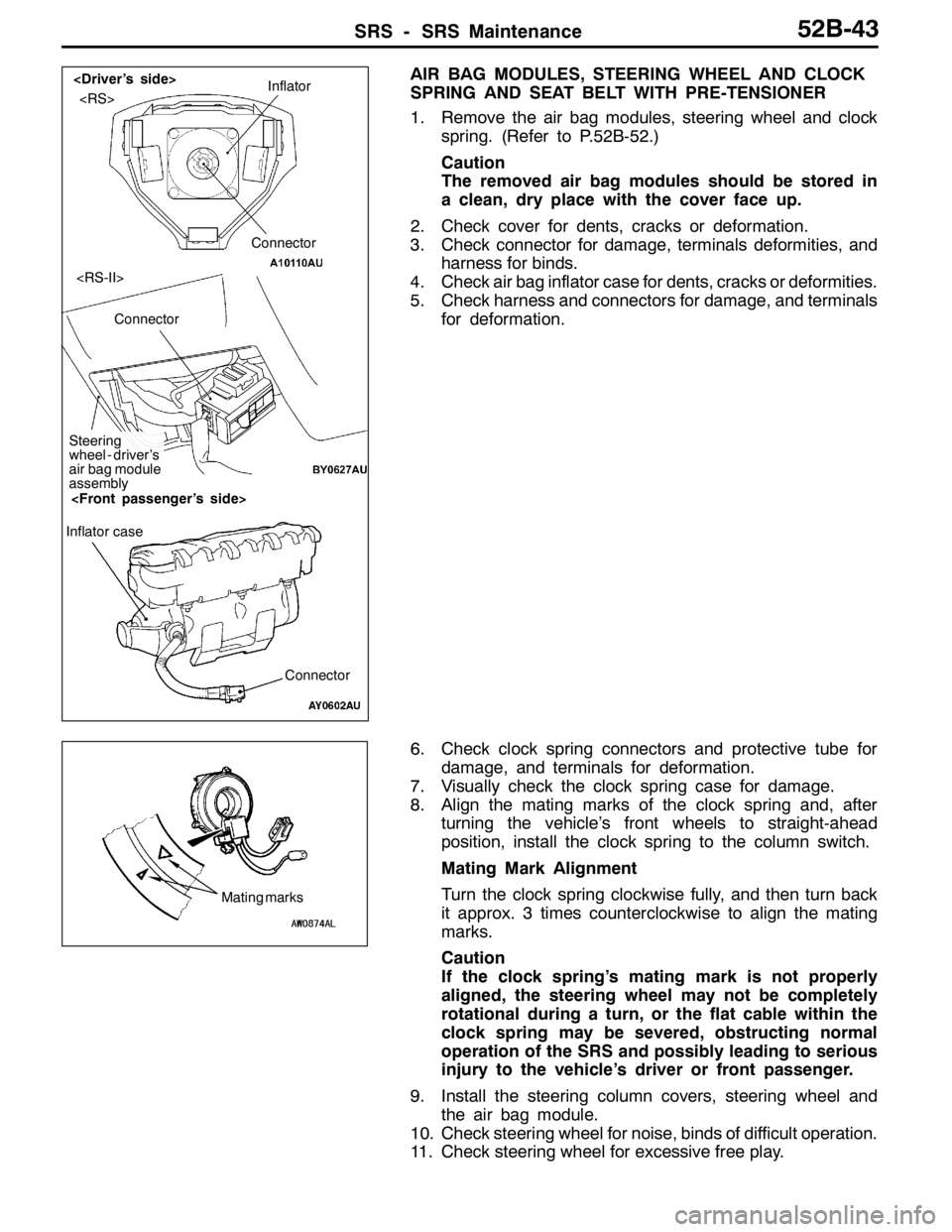
AIR BAG MODULES, STEERING WHEEL AND CLOCK
SPRING AND SEAT BELT WITH PRE-TENSIONER
1. Remove the air bag modules, steering wheel and clock
spring. (Refer to P.52B-52.)
Caution
The removed air bag modules should be stored in
a clean, dry place with the cover face up.
2. Check cover for dents, cracks or deformation.
3. Check connector for damage, terminals deformities, and
harness for binds.
4. Check air bag inflator case for dents, cracks or deformities.
5. Check harness and connectors for damage, and terminals
for deformation.
6. Check clock spring connectors and protective tube for
damage, and terminals for deformation.
7. Visually check the clock spring case for damage.
8. Align the mating marks of the clock spring and, after
turning the vehicle’s front wheels to straight-ahead
position, install the clock spring to the column switch.
Mating Mark Alignment
Turn the clock spring clockwise fully, and then turn back
it approx. 3 times counterclockwise to align the mating
marks.
Caution
If the clock spring’s mating mark is not properly
aligned, the steering wheel may not be completely
rotational during a turn, or the flat cable within the
clock spring may be severed, obstructing normal
operation of the SRS and possibly leading to serious
injury to the vehicle’s driver or front passenger.
9. Install the steering column covers, steering wheel and
the air bag module.
10. Check steering wheel for noise, binds of difficult operation.
11. Check steering wheel for excessive free play.Inflator
Connector
Connector
Steering
wheel - driver’s
air bag module
assembly
Connector Inflator case
Mating marks
Page 1290 of 1449

SRS - Post-collision Diagnosis52B-46
REPAIR PROCEDURE
DEPLOYED DRIVER’S AND FRONT PASSENGER’S AIR
BAGS OR OPERATED SEAT BELT PRE-TENSIONER.
1. Replace the following parts with new ones.
DSRS-ECU (Refer to P.52B-50.)
DDriver’s air bag module (Refer to P.52B-52.)
DFront passenger’s air bag module (Refer to P.52B-52.)
DSeat belt with pre-tensioner (Refer to P.52B-61.)
2. Check the following parts and replace if malfunction is
found:
DClock spring (Refer to P.52B-52.)
DSteering wheel, steering column and intermediate
joint
(1) Check the wiring harness (built into steering
wheel) and connectors for damage, and terminals
for deformation.
(2) Check the driver’s air bag module for proper
installation to the steering wheel.
(3) Check the steering wheel for noise, binds or
difficult operation and excessive free play.
3. Check the harness for binding, connectors for damage,
poor connections, and terminals for deformation.
(Refer to P.52B-44.)
UNDEPLOYED AIR BAGS OR UNOPERATED SEAT BELT
WITH PRE-TENSIONER IN LOW-SPEED COLLISION
Check the SRS components and seat belt with pre-tensioner.
If visible damage such as dents, cracks, or deformation are
found on the SRS components and seat belt with
pre-tensioner, replace them with new ones. Concerning parts
removed for inspection, replacement with new parts and
cautions in working, refer to INDIVIDUAL COMPONENT
SERVICE, P.52B-49.
Page 1292 of 1449

SRS - Post-collision Diagnosis52B-48
Steering wheel, steering column and intermediate joint
1. Check the driver’s air bag module for proper installation
to the steering wheel.
2. Check the steering wheel for noise, binds or difficult
operation and excessive free play.
Harness connector (Instrument panel wiring harness,
Floor wiring harness)
Check the harness for binds, the connector for damage and
the terminals for deformation. (Refer to P.52B-44.)
Seat belt with pre-tensioner
1. Check the seat belt for damage or deformation.
2. Check the pre-tensioner for cracks or deformation.
3. Check the harness or the connector for damage, and
the terminal for deformation.
4. Check that the unit is installed correctly to the vehicle
body.
Page 1293 of 1449

SRS - Individual Component Service/Warning/Caution Labels52B-49
INDIVIDUAL COMPONENT SERVICE
If the SRS components and seat belt with pre-tensioner are to be removed or replaced as a result of
maintenance, troubleshooting etc., follow the service procedures that follow.
Caution
1. SRS components and seat belt with pre-tensioner should not be subjected to heat, so remove
the SRS-ECU, driver’s air bag module
passenger’s air bag module, clock spring, and seat belt with pre-tensioner before drying or
baking the vehicle after painting.
DFront impact sensor, SRS-ECU, Air bag module, clock spring: 93_C or more
DSeat belt with pre-tensioner: 90_C or more
Recheck SRS system operability after re-installing them.
2. If the SRS components and seat belt with pre-tensioner are removed for the purpose of check,
sheet metal repair, painting, etc., they should be stored in a clean, dry place until they are
reinstalled.
WARNING/CAUTION LABELS
Caution labels on the SRS are attached in the
vehicle as shown. Follow label instructions whenservicing the SRS. If the label(s) are dirty or
damaged, replace with new one(s).
Steering wheel
Driver’s air bag module
Clock springFront passenger’s
air bag moduleSRS-ECU
Sun visor
Steering joint cover
Glove boxCover
Seat belt with pre-tensioner
Page 1305 of 1449

SRS -Seat Belt with Pre-tensioner52B-61
SEAT BELT WITH PRE-TENSIONER
Caution:
1. Wait for at least 60 seconds after
disconnecting the negative ( - ) terminal of
the battery before starting any operation.The
removed negative ( - ) terminal must be
protected by wrapping the tape. (Refer to
P.52B-3.)
2. Never disassemble or repair the seat belt
with pre-tensioner. Replace the part with a
new one when it malfunctions.
3. Take an extra care to deal with the seat belt
with pre-tensioner by avoiding dropping or
wetting it with water or oil. If any dent, crack,
or deformation is found, be sure to replace
the seat belt with pre-tensioner with a new
part.4. Do not place a heavy object on top of the
seat belt pre-tensioner.
5. Never keep the seat belt with pre-tensioner
in a place where the temperature can exceed
over 90_C.
6. Replace the seat belt with pre-tensioner with
a new one after operating the seat belt
pre-tensioner.
7. Wear gloves or protective glasses when
handling the seat belt with pre-tensioner
after operation.
8. If the seat belt with pre-tensioner before
operation needs to be discarded, be sure
to do so after operating the seat belt
pre-tensioner. (Refer to P.52B-64.)
REMOVAL AND INSTALLATION
Pre - removal operation
DTurn the ignition key to the LOCK(OFF) position.
DDisconnect the negative ( - ) terminal of the battery.
1 4
3
2
44±10 NSm
44±10 NSm
5
Removal steps
1. Sash cover guide
2. Seat belt lower anchor bolt
3. Bracket
4. Seat belt shoulder anchor bolt
DCenter pillar lower trim
(Refer to GROUP 52A - Trim.)
5. Seat belt pre-tensionerInstallation steps
"AA
DPre - installation inspection
5. Seat belt pre-tensioner
4. Seat belt shoulder anchor bolt
3. Bracket
2. Seat belt lower anchor bolt
DCenter pillar lower trim
(Refer to GROUP 52A - Trim.)
1. Sash cover guide
DNegative ( - ) terminal of the battery
connection
"BADPost - installation inspection
Page 1306 of 1449

SRS -Seat Belt with Pre-tensioner52B-62
INSTALLATION SERVICE POINTS
"AAPRE-INSTALLATION INSPECTION
1. Pre-installation inspection must be carried out even when
installing a new seat belt with pre-tensioner. (Refer to
Inspections.)
Caution
If the seat belt with pre-tensioner is discarded, discard
it after operating the seat belt pre-tensioner according
to the specified procedure. (Refer to P.52B-64.)
2. Connect the negative ( - ) terminal of the battery.
3. Connect the MUT-II to the diagnosis connector (16 pin).
Caution
Connection and disconnection of the MUT-II must be
carried out after turning the ignition switch to the
LOCK (OFF) position.
4. Turn the ignition switch to ON position.
5. Check that there is no abnormality except for open circuit
in the seat belt pre-tensioner after reading diagnostic
codes.
6. Turn the ignition key to LOCK (OFF) position.
7. Release the negative ( - ) terminal cable of the battery
and wrap a tape around it for insulation.
Caution
Wait for at least 60 seconds after disconnecting the
negative ( - ) battery cable before starting any
operation. (Refer to P.52B-3.)
"BAPOST-INSTALLATION INSPECTION
1. Turn the ignition switch to the ON position.
2. Check that the SRS warning lamp illuminates for 6 to
8 seconds and goes out.
3. Carry out troubleshooting if the lamp does not go out.
(Refer to P.52B-6.)
SRS warning lamp
Page 1307 of 1449

SRS -Seat belt with Pre-tensioner52B-63
INSPECTION
SEAT BELT PRE-TENSIONER
If any faulty is discovered by the following inspections, replace
the seat belt with pre-tensioner with a new one.
Discard the old parts according to the specified procedure
after operating the seat belt pre-tensioner.(Refer to P.52B-64.)
Caution
Do not measure the circuit resistance of the seat belt
pre-tensioner even if it is done with a specified tester.
If a tester is used to measure the circuit resistance, squib
charged with current or erroneous activation by static may
cause critical damage.
1. Seat belt pre-tensioner for dent, crack, or deformation
2. Harness or connector for damage and terminal for
deformation